









Overview
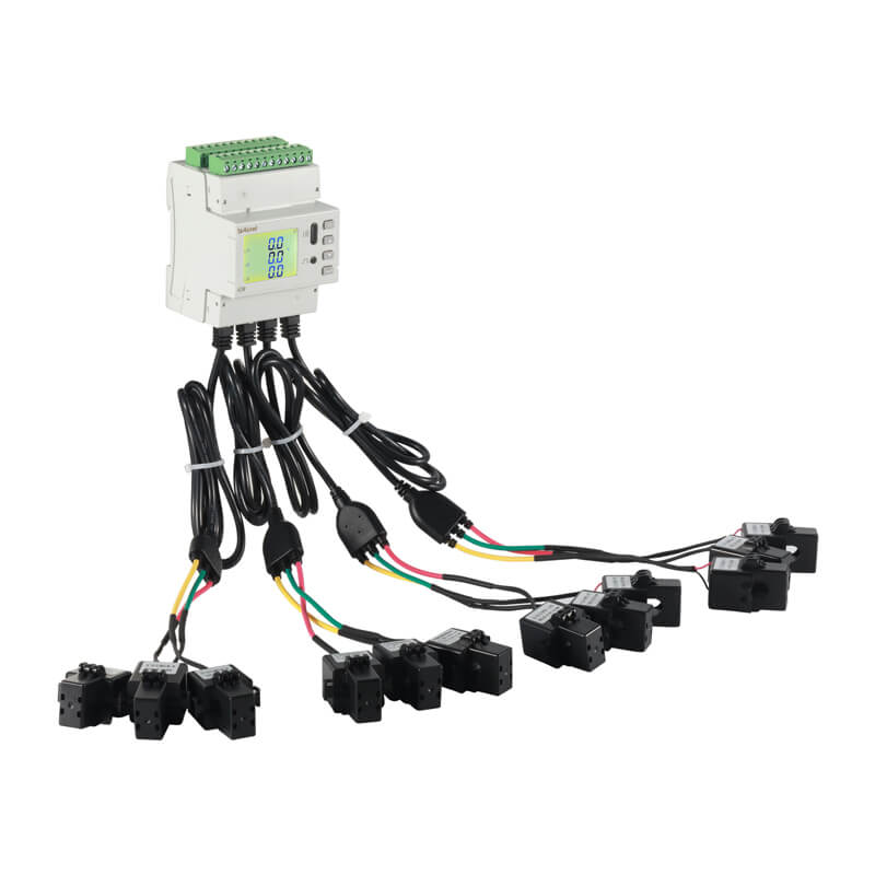
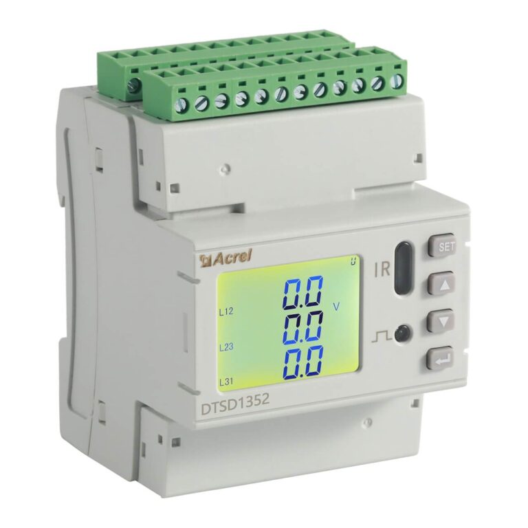
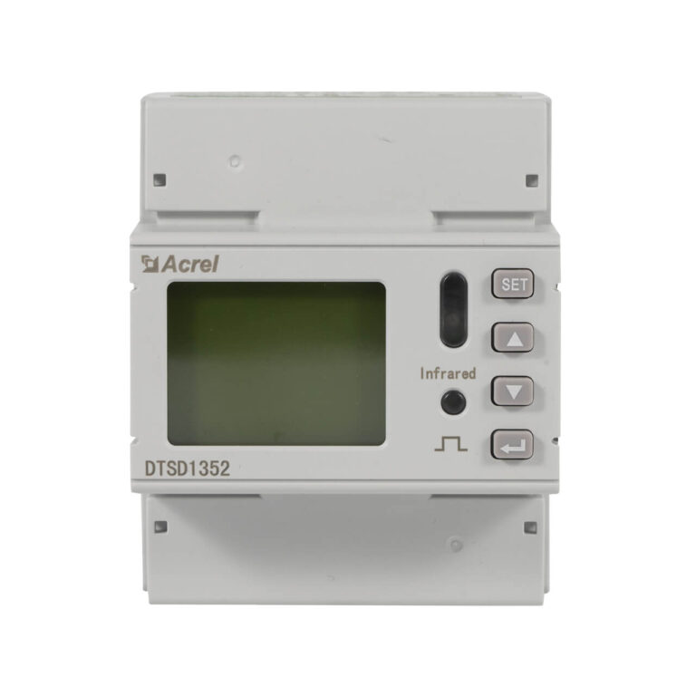
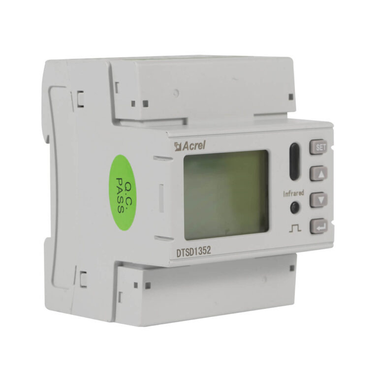
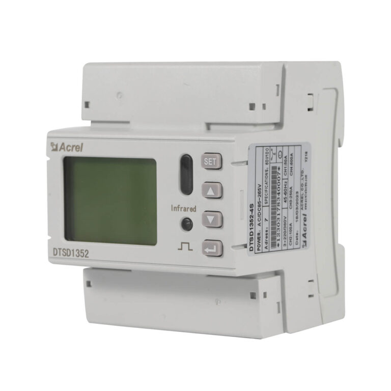
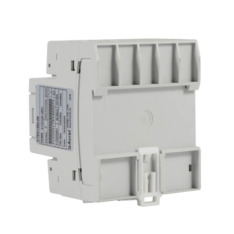
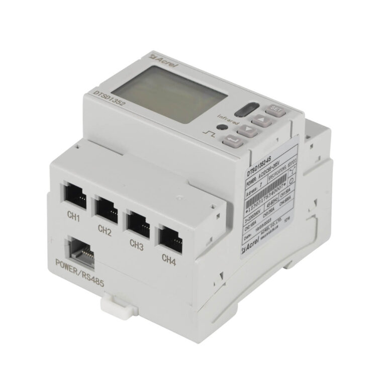
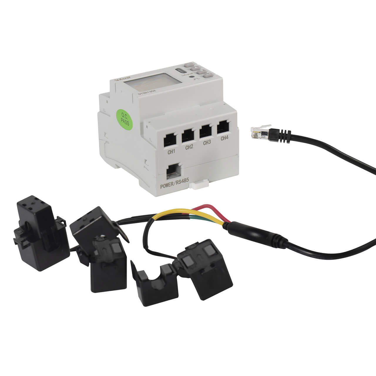
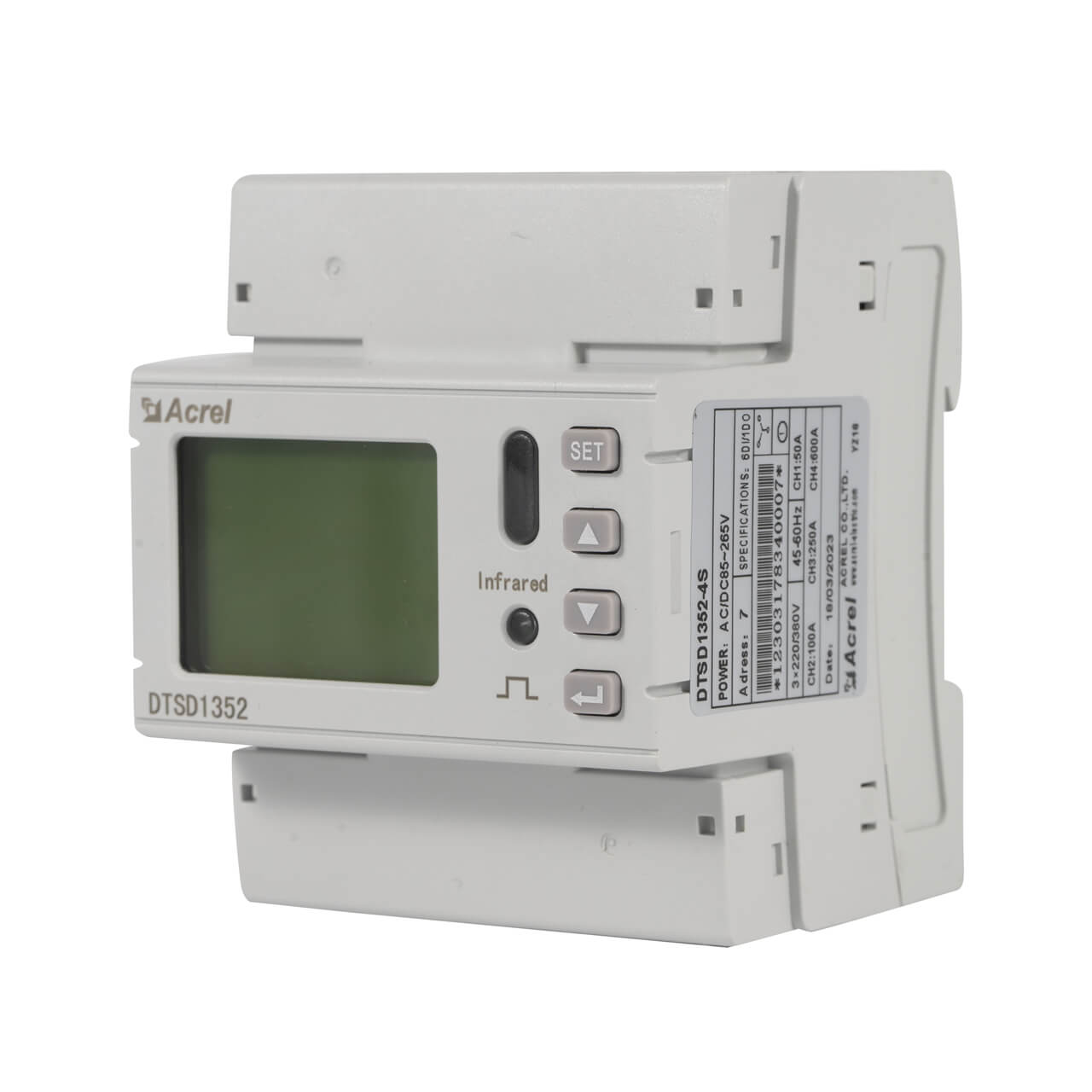
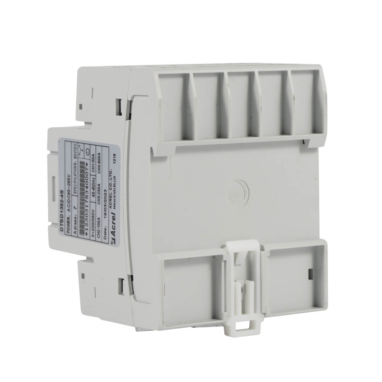
The DTSD1352-4S is a rail-type multi-circuit power meter designed for modern power distribution systems.
It addresses the issues of traditional solutions that require multiple meters for monitoring several circuits, which take up significant space and increase costs.
With just one DTSD1352-4S, you can simultaneously monitor the complete electrical parameters of 4 three-phase circuits or 12 single-phase circuits.
It is not just an energy metering tool but a comprehensive power monitoring terminal, measuring voltage, current, power, energy, demand, unbalance, and 2nd to 31st harmonics.
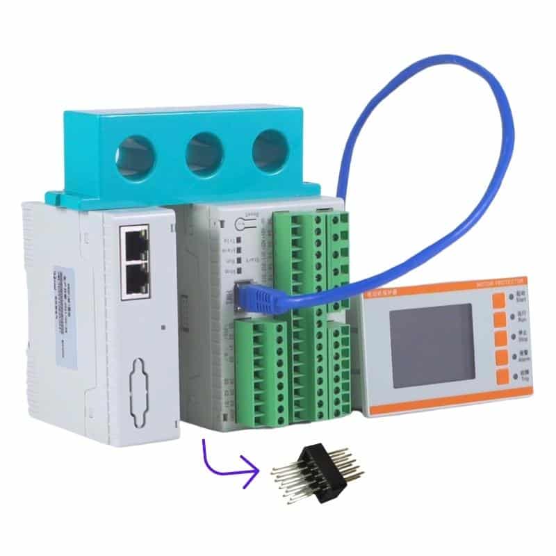
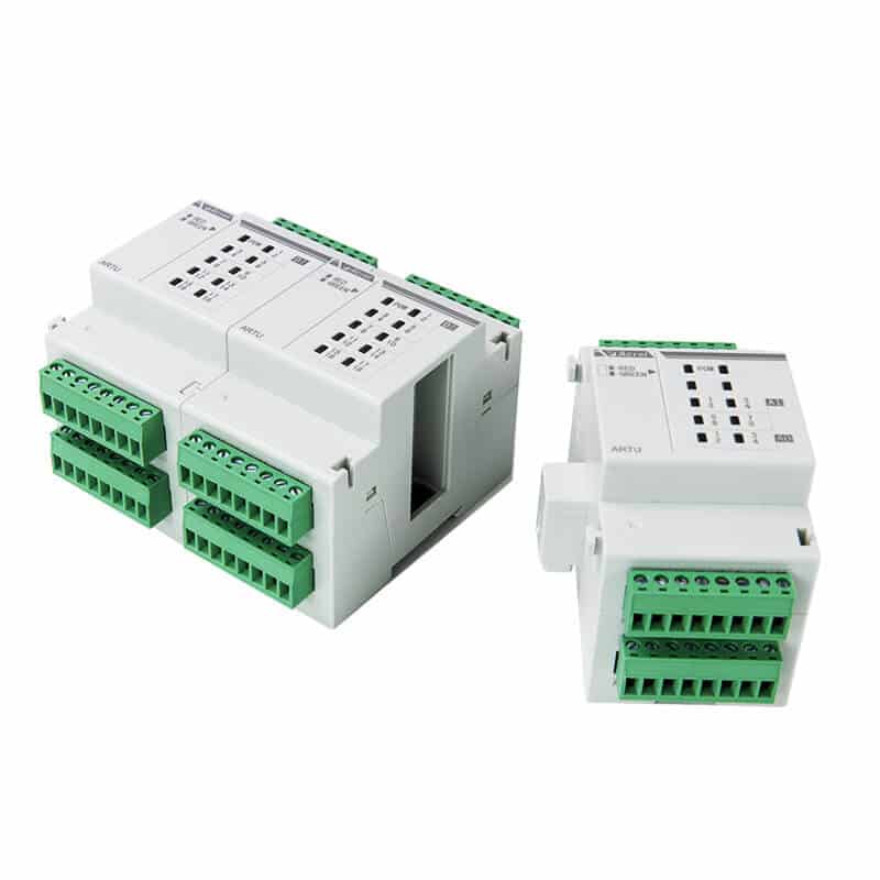
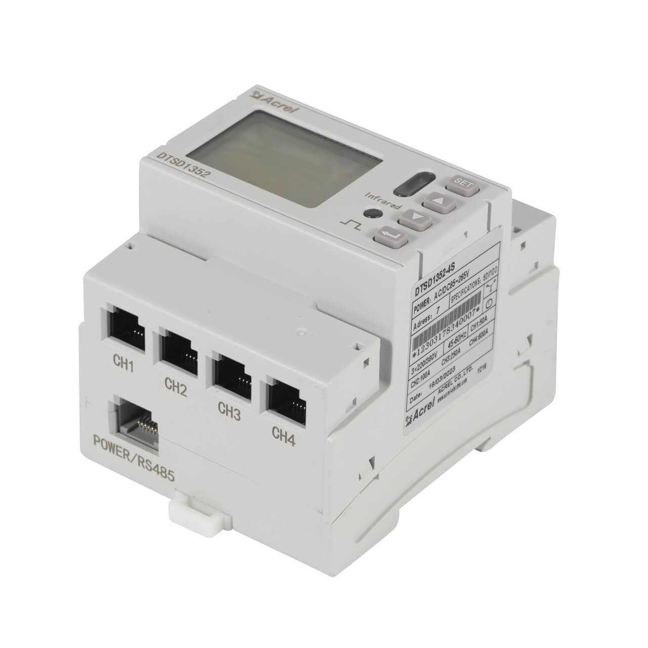
Its powerful expandability allows for flexible implementation of digital input/output monitoring, temperature measurement, leakage current monitoring, and wireless communication via external modules.
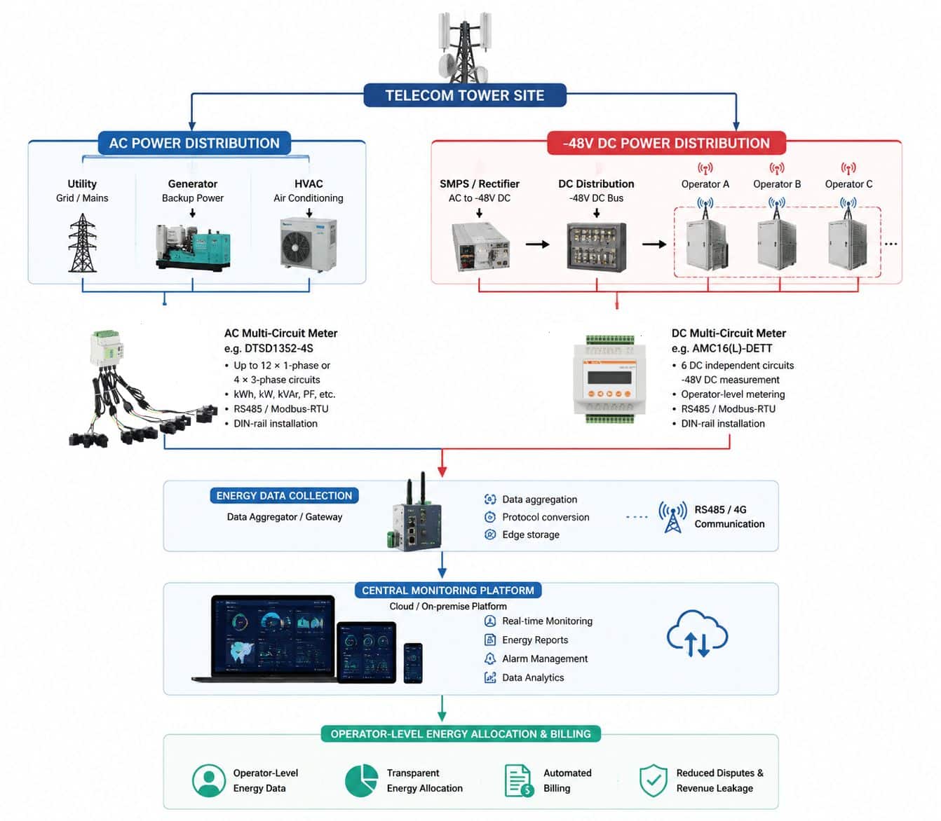
It is an ideal choice for refined energy management in industrial parks, Telecom Sites, commercial buildings, and data centers.
Highlight
Multi-Circuit Measurement
- Monitors 4 three-phase or 12 single-phase circuits with one device;
- Measures full electrical parameters: V, A, W, PF, harmonics 2~31, unbalance.
Modular Expansion
- RJ45 interface for plug-and-play expansion modules;
- MK: 12DI + 4DO;
- MTL: 12 temp + 4 leakage;
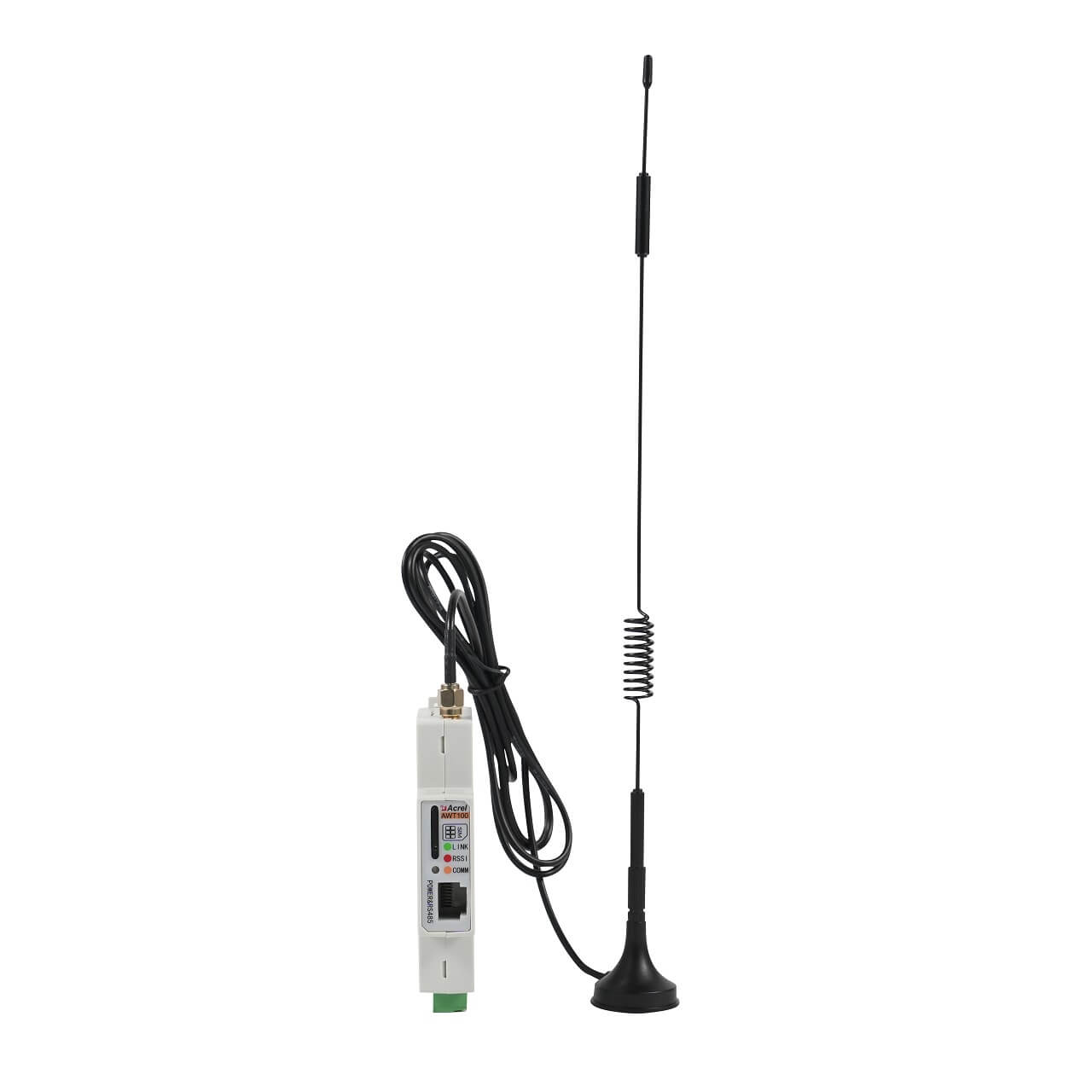
- AWT series: 2G/4G/NB-IoT/LoRa/LoRaWAN.
High Accuracy & Reliability
- Voltage/current: Class 0.5;
- Active energy: Class 1.0;
- Reactive energy: Class 2.0;
- Harmonics: ±1%.
Data Logging & Event Recording
- Monthly max/min with timestamps;
- 200 event logs (alarms/DI actions);
- 12-month historical tariff data;
- 31-day daily energy freeze.
Function
| Measurement | Metering | Other |
| Voltage, current, frequency | Forward/Reverse active & reactive energy | Configurable as 4 three-phase or 12 single-phase circuits |
| Active/Reactive/Apparent power | Four-quadrant energy | 31-day daily freeze & 12-month historical energy |
| Power factor, phase angle | Multi-tariff energy (4 tariffs, 14 periods) | 200 event logs (alarms/DI actions) |
| Voltage/Current unbalance | Demand (current/power, current/previous month) | RS485 communication (Modbus-RTU) |
| 2nd–31st harmonics (V/I THD) | Extreme values (V/I/P with timestamps) | Optional Ethernet (Modbus-TCP) |
| Zero-sequence current | Optional digital I/O: 6DI+1DO or 2DI+2DO | |
| Supports expansion modules (MK/MTL/AWT100 series) |
Specification
| Parameter | Specification |
| Input Voltage | AC 3×220V/380V, rated value Overload: 1.2× continuous, 2× for 1s |
| Input Current | 50mA / 100mV / 333mV optional (requires external current sensor) Overload: 1.2× continuous, 10× for 1s |
| Accuracy | Voltage/Current: Class 0.5 Active Energy: Class 1 Reactive Energy: Class 2 (Excluding sensors) |
| Harmonic Measurement | 2nd–31st, accuracy: ±1% |
| Auxiliary Power | AC/DC 85~265V or DC 40~60V (optional DC 9~36V) Power consumption: ≤10VA |
| Operating Environment | Temperature: -20℃~+60℃ Humidity: ≤95% non-condensing Altitude: ≤2500m |
| Communication Interface | 1x RS485 (Modbus-RTU) Optional 1x RJ45 (Modbus-TCP), model DTSD1352-4S/CE |
| Digital I/O | Optional configurations: ① 6DI + 1DO (4 dry + 2 wet 220V AC) ② 2DI + 2DO (2 dry) |
| Expansion Module Interface | Supports MK, MTL, AWT100 series modules |
| Dimensions | Main unit: 126mm × 85mm × 70mm (including terminals) |
| Mounting | 35mm DIN rail |
Show More
Compatible Sensors
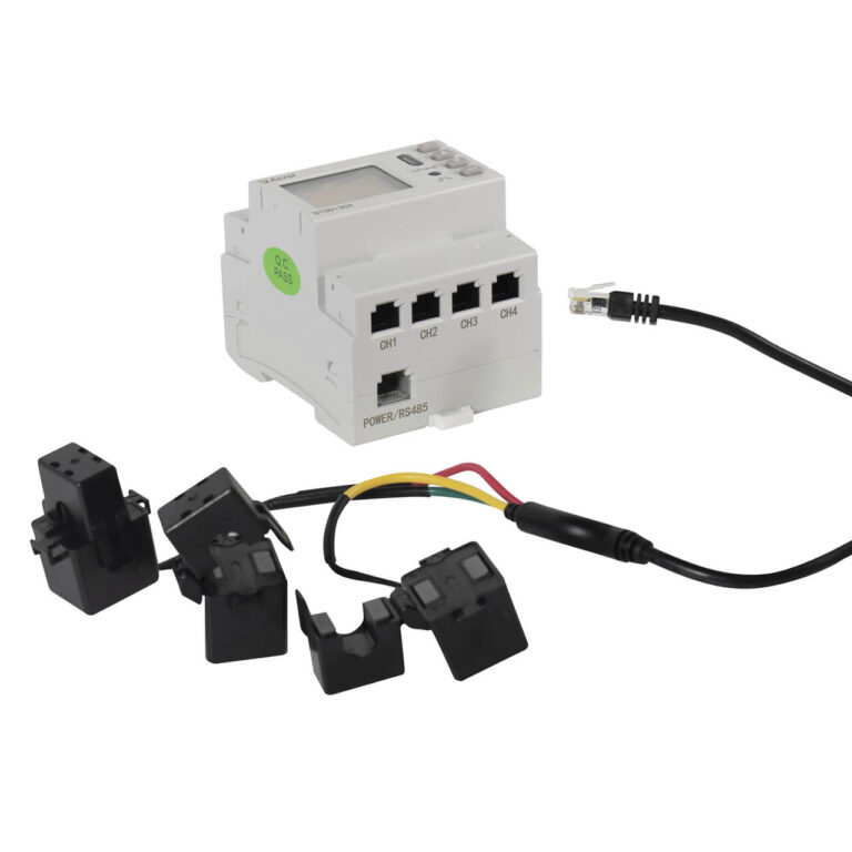
The meter requires external current sensors with an RJ45 interface for easy installation. Various types are available for different site needs:
- 3-in-1 Closed-core CTs: e.g., AKH-0.66/W series, high accuracy, suitable for new installations.
- 3-in-1 Split-core CTs: e.g., AKH-0.66/K series, installation without disconnecting the primary conductor, ideal for retrofit projects.
- Rogowski Coils: e.g., BR-90N, suitable for high-current or space-constrained applications.
Selection Tip: When ordering, specify the sensor output type (mA/mV) and rating. The corresponding current ratio must be set on the meter. For Rogowski coils, the sensor type must be configured via dedicated software.
Summary
The DTSD1352-4S multi-circuit power meter redefines solutions for multi-circuit monitoring scenarios with its high integration, high accuracy, and flexible expandability. It simplifies complex multi-circuit monitoring needs into a single device, reducing procurement and installation costs while saving valuable distribution space. Whether for refined design in new projects or energy-saving retrofits in existing systems, the DTSD1352-4S provides a powerful, reliable, and easily integrated data foundation, helping your power distribution system move towards digitalization and intelligence.
FAQ
Selection mainly depends on communication and I/O needs. Choose the /CE suffix model for Ethernet communication. For I/O, choose the 6DI+1DO model for more inputs, or the 2DI+2DO model for more outputs or if only dry contacts are needed.
Theoretically, multiple modules can be daisy-chained via Ethernet cable, but considering communication efficiency, it is recommended to cascade 1-2 modules (e.g., one MK and one MTL) in practice. Consult technical support for details.
You can set the primary current value for each circuit (CH1~CH4) individually via the meter’s panel in the “Signal Input” menu, or by writing to the corresponding Modbus registers (addresses 14H~17H). Please refer to Chapter 3 of the manual for the specific calculation formula.
This can be configured in the “Alarm Setting” menu. First, select the alarm mode (e.g., overvoltage, overcurrent), then specify the target circuit, delay time, hysteresis, and alarm thresholds (high/low limits). The relay can be set to remote mode or associated with specific alarms.
Please check: 1) RS485 A/B wiring is correct (A to A, B to B). 2) The communication address, baud rate, and parity settings match the host computer. 3) A 120Ω termination resistor is connected at the end of the bus (especially for long-distance communication). 4) Test with only one device online to rule out address conflicts.