

Application in Operating Room, ICU and CCU
Overview
The core of the IT system insulation monitoring and fault location solution is to supply power via isolation transformers and perform 24/7 uninterrupted monitoring of the line insulation condition. In high‑risk environments such as operating rooms, ICUs and CCUs, this protects patients and medical staff from electric leakage and ensures uninterrupted operation of critical medical equipment.
How does it work?
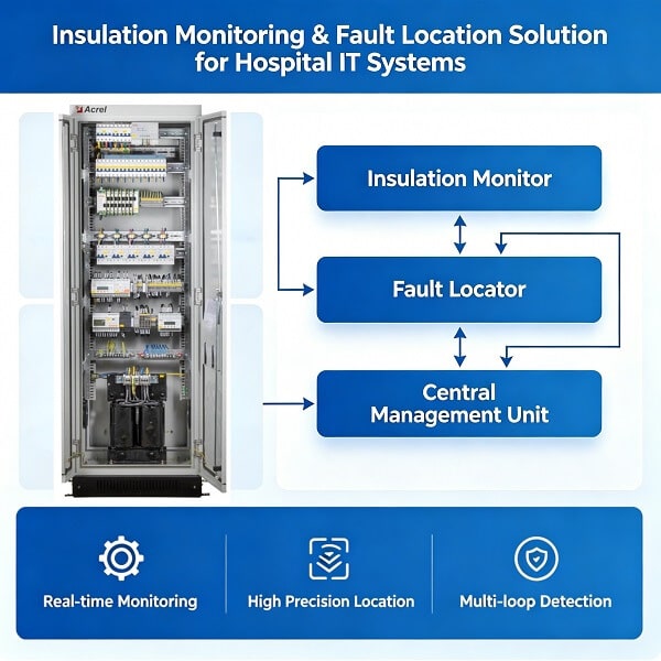
The system is not a single device but a complete, coordinated system. Its operating logic and technical components are as follows:
1. Core Logic
Source isolation: Use an isolation transformer to convert the mains power (TN system) into an ungrounded IT system. Thus, even if a device enclosure becomes accidentally live, no circuit can be formed to ground, fundamentally avoiding electric leakage risk.
Continuous monitoring: The insulation monitor acts as the “neural center”, continuously monitoring the insulation resistance, transformer temperature and load current of the entire IT system.
Intelligent fault location: Once an insulation fault occurs, the system immediately gives an audible and visual alarm. At the same time, a test signal generator injects a specific signal into the line, and the insulation fault locator, like a “detector”, captures this signal through built‑in high‑precision current transformers, thereby accurately pinpointing the faulty circuit.
2. Key Technical Components
AITR series isolation transformer: Provides electrical isolation and converts the TN system into an IT system. Its turns ratio is 1:1, the windings have double insulation and an electrostatic shield, and a built‑in PT100 temperature sensor monitors winding temperature.
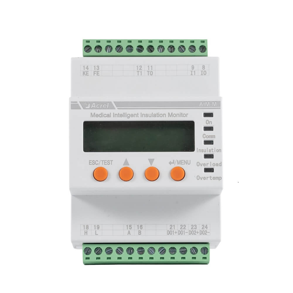
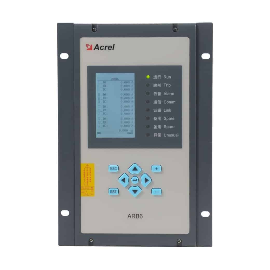
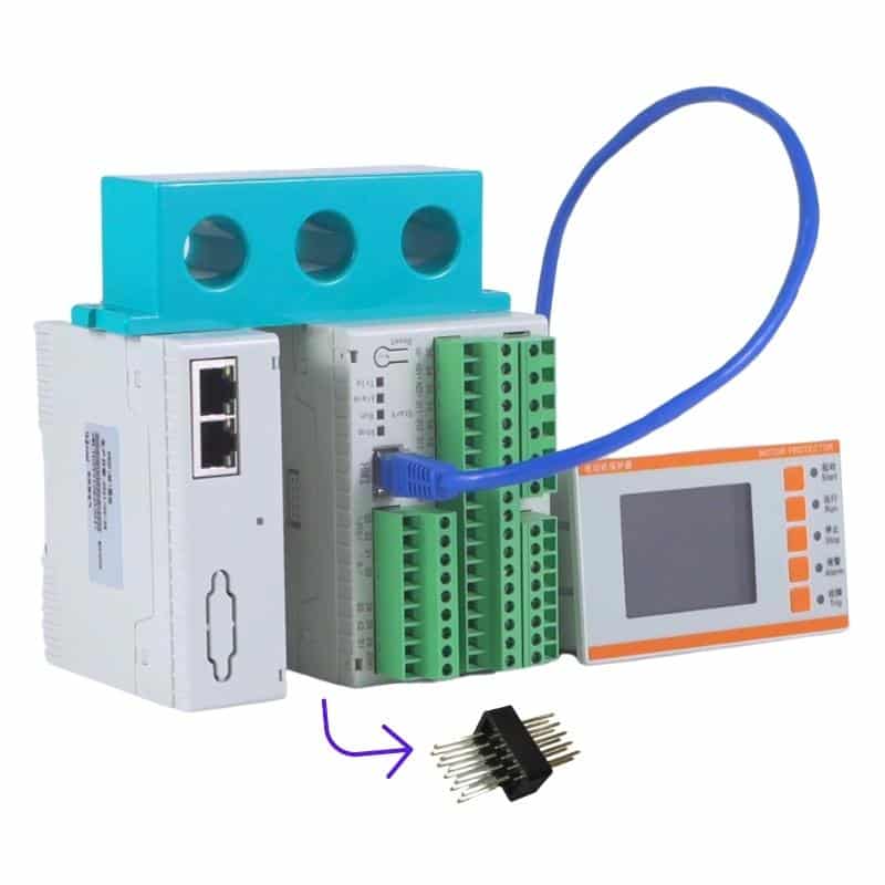
AIM‑M series insulation monitor: Real‑time monitoring of the IT system’s insulation resistance to ground, transformer load current and winding temperature. It issues an alarm within 2 seconds upon detecting an anomaly or a wiring break fault.
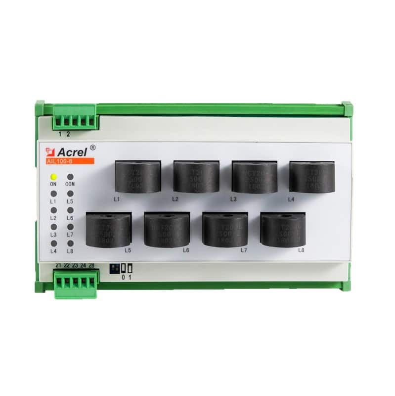
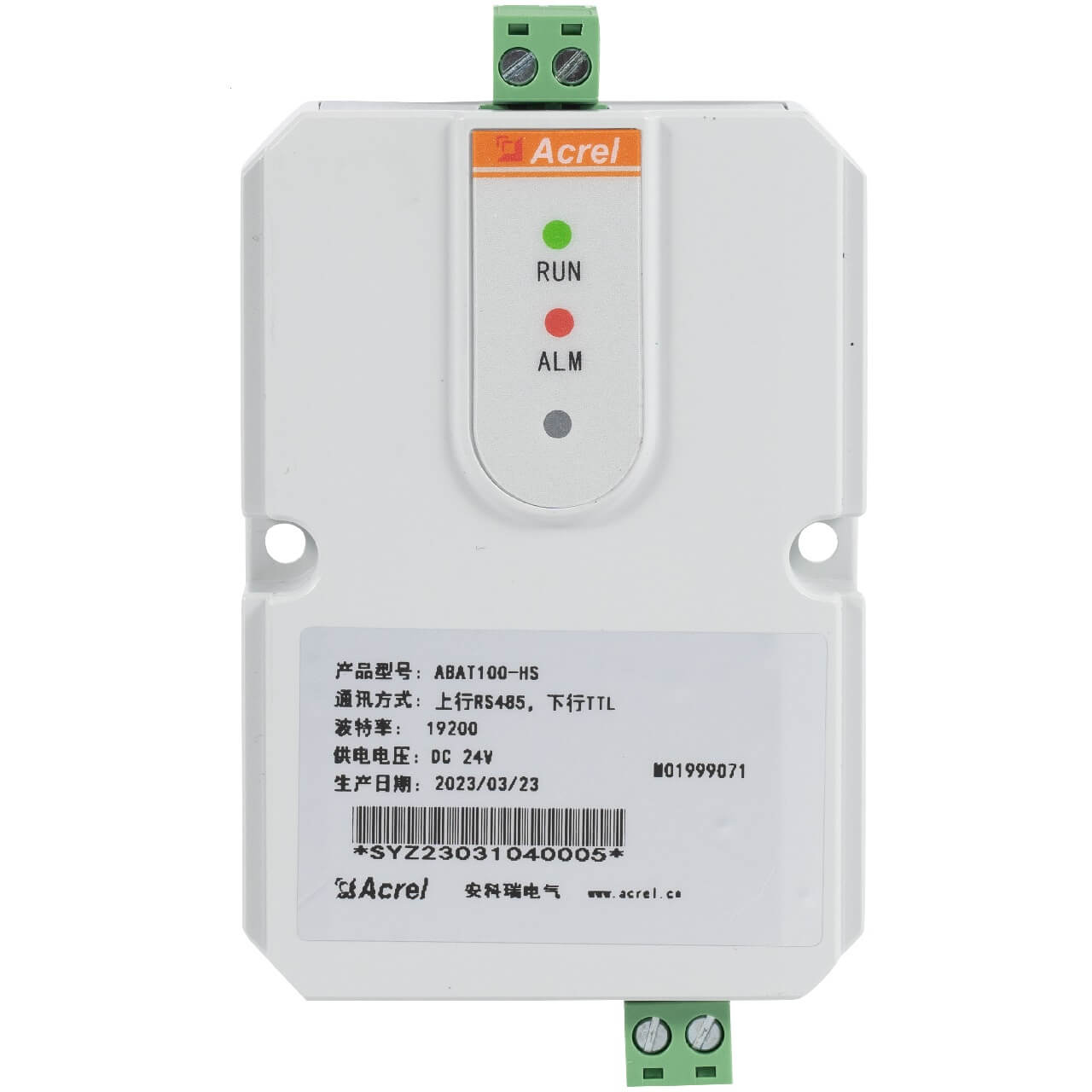
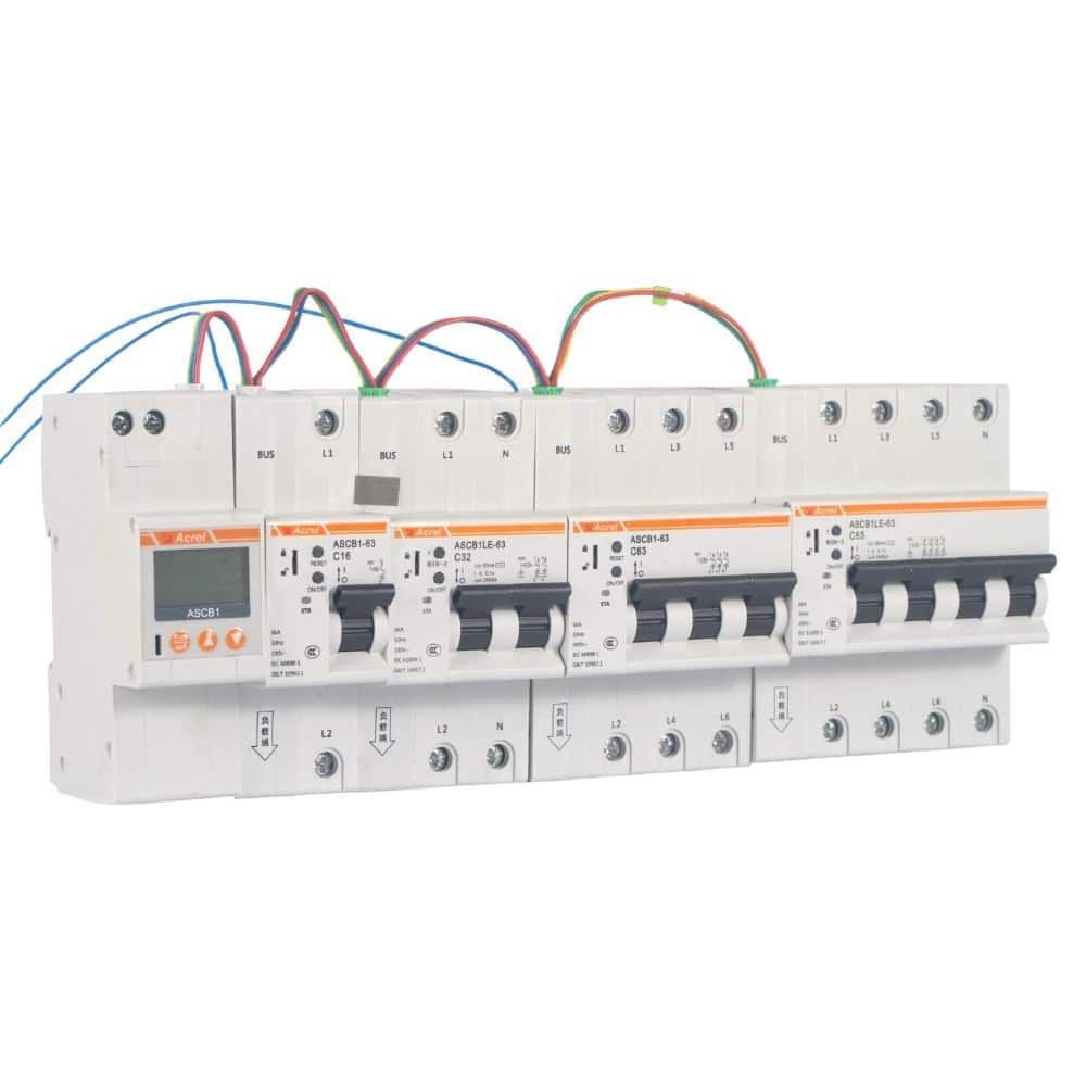
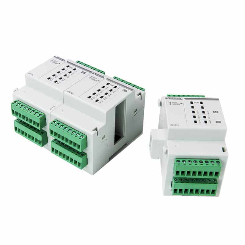
AIL series fault locator: Captures the injected locating signal through built‑in high‑precision current transformers, thereby accurately pinpointing the specific faulty circuit. For example, model AIL150‑4 can locate up to 4 circuits, while AIL150‑8 can locate up to 8 circuits.
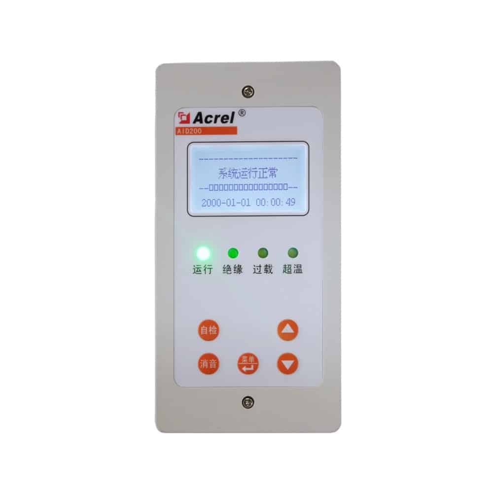
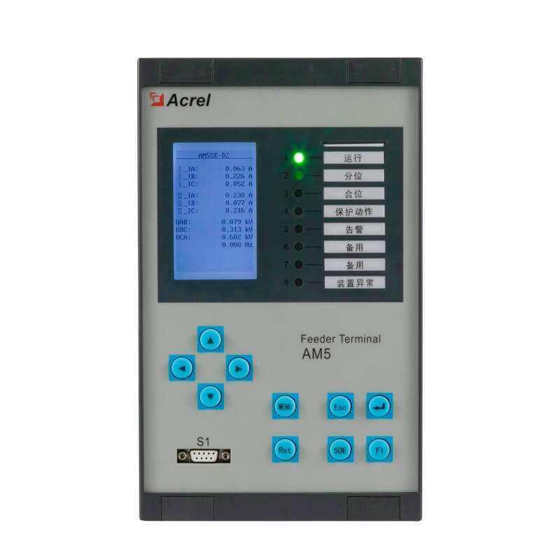
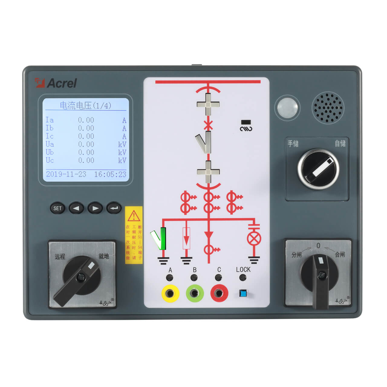
AID series alarm display unit: Installed at locations such as nurse stations for centralized display and alarming. It can remotely monitor the status of up to 16 IT systems and provides audible/visual alarms and historical event logging.
Topology
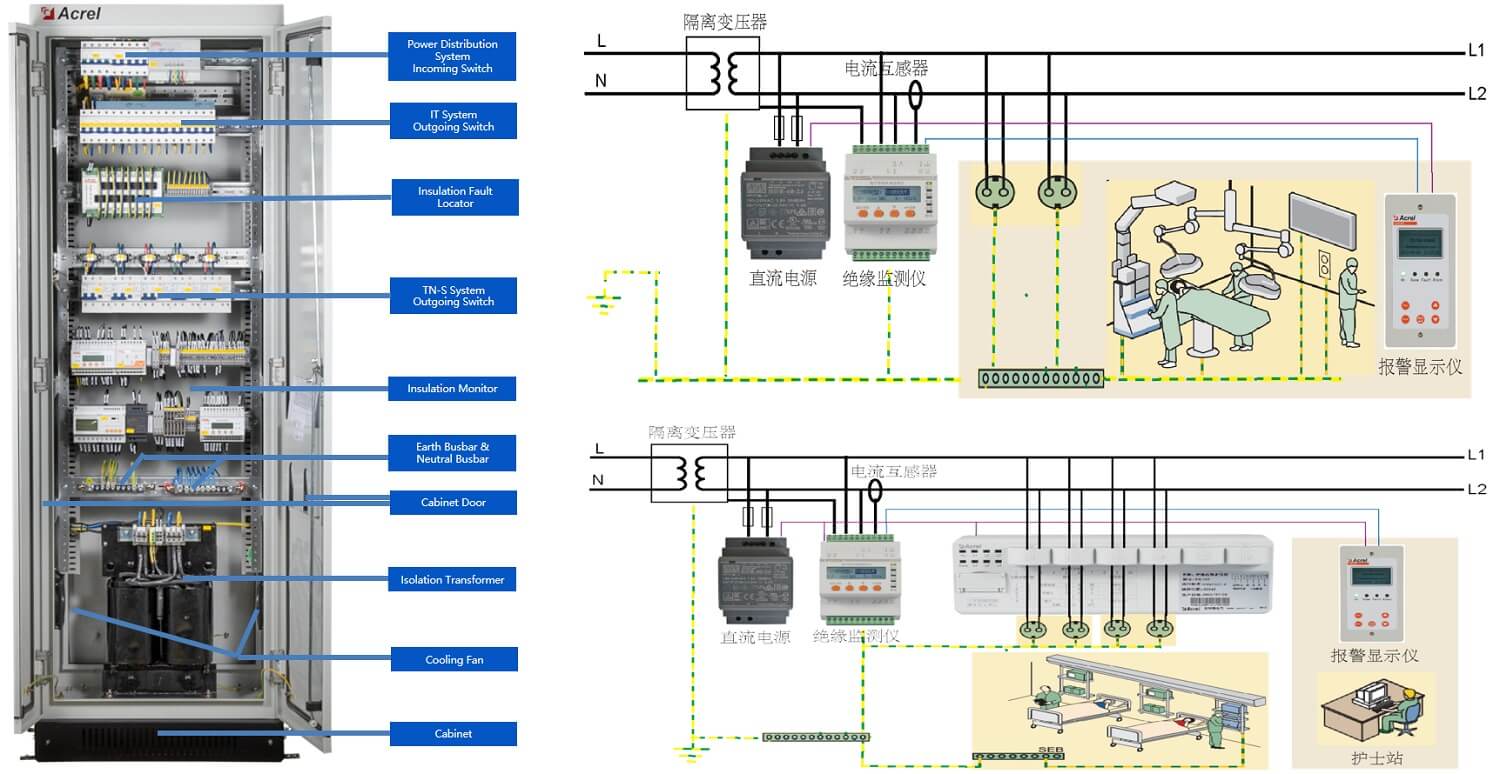
Specific Applications in Different Scenarios
| Scenario | Core Goal | Key Function |
| Operating Room | High‑precision monitoring, ensure continuous power to life‑support equipment | The system monitors insulation resistance in real time; in case of a single ground fault, it only alarms but does not trip, ensuring surgical safety. |
| ICU | Continuous monitoring of equipment for critically ill patients | Provides uninterrupted power to ventilators, monitors, etc., avoiding equipment shutdown due to electrical faults that could endanger patients’ lives. |
| CCU | Rapid fault location, ensure availability of cardiovascular equipment | Focuses on power supply to cardiovascular equipment; the system quickly locates and displays the faulty circuit, helping technicians promptly clear the fault and ensure continuous equipment operation. |
Key Advantages of the Application
Ensures uninterrupted “life‑critical power”: During surgery, even a tiny leakage current can be fatal. The greatest value of the IT system is that when the first ground fault occurs, the system only alarms but does not trip like a conventional system, thereby ensuring continuous power supply to “life‑support systems” such as ventilators, monitors and surgical equipment.
Achieves “minute‑level” fault diagnosis: In ICUs and CCUs, there are many devices and complex wiring. Traditional fault diagnosis is like “looking for a needle in a haystack”. The fault location function reduces diagnosis time from hours to minutes. The system directly tells maintenance personnel “which circuit” is faulty, greatly improving troubleshooting efficiency.
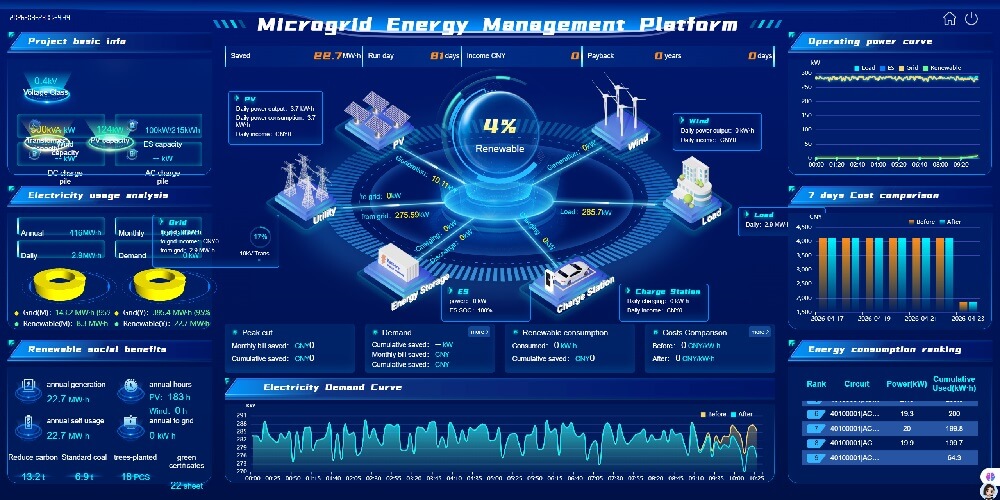
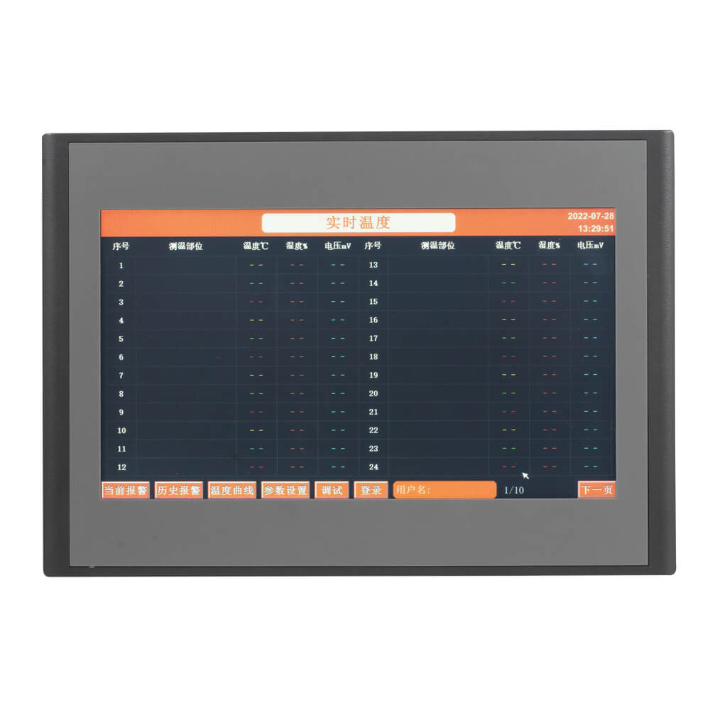
Centralized monitoring, unified management: Through a central monitoring system, hospital electrical managers can view the operating status of all IT systems in every operating room, ICU and CCU on a single platform (e.g. a touch screen in the control room), including key parameters such as insulation resistance, load rate and transformer temperature, achieving centralized, visual and intelligent management.
Conslusion
In summary, through its two core technologies – isolated power supply and intelligent monitoring – this system elevates the electrical safety of critical medical areas such as operating rooms, ICUs and CCUs from a level of passive protection to active defense, building a solid electrical safety barrier for medical activities.