







Overview
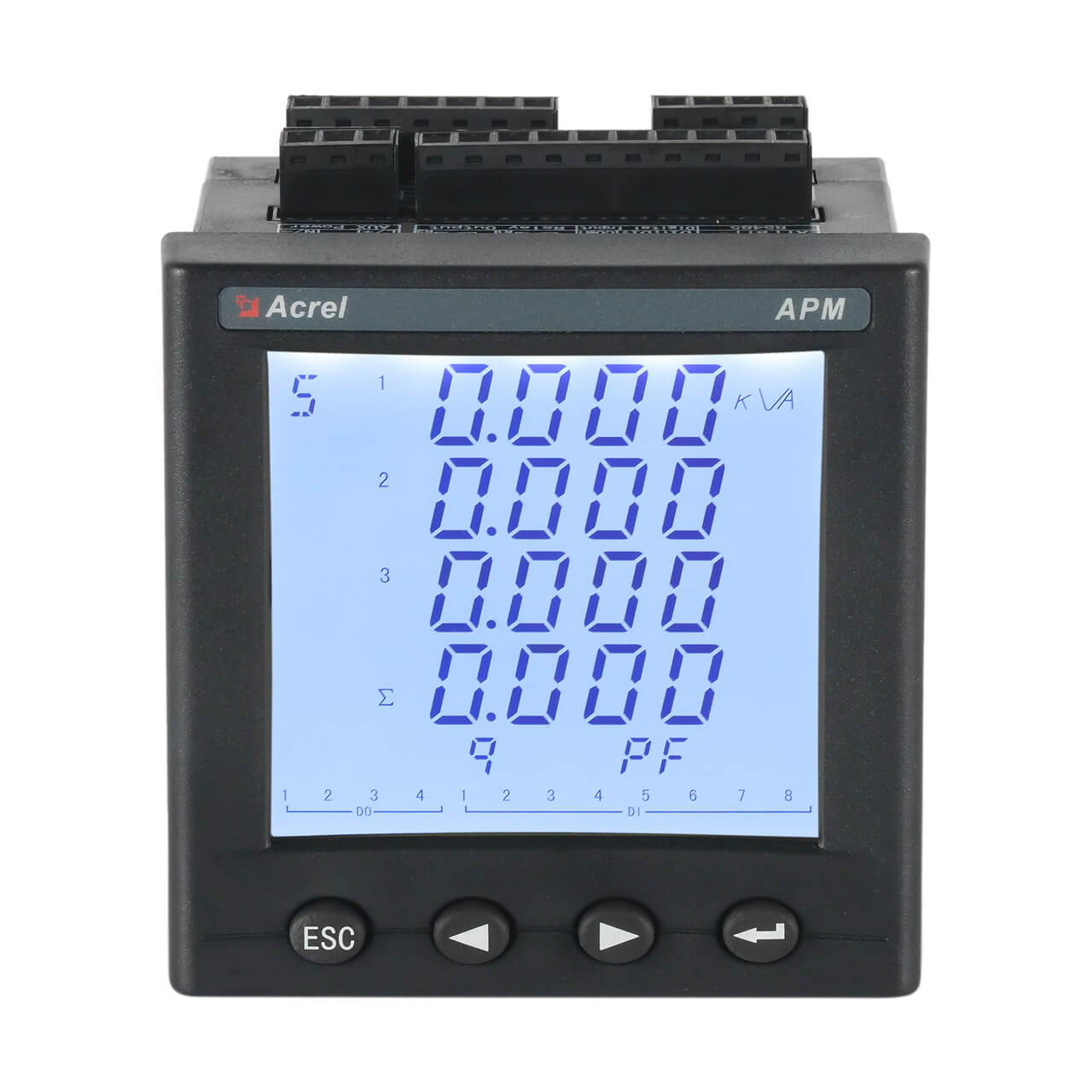
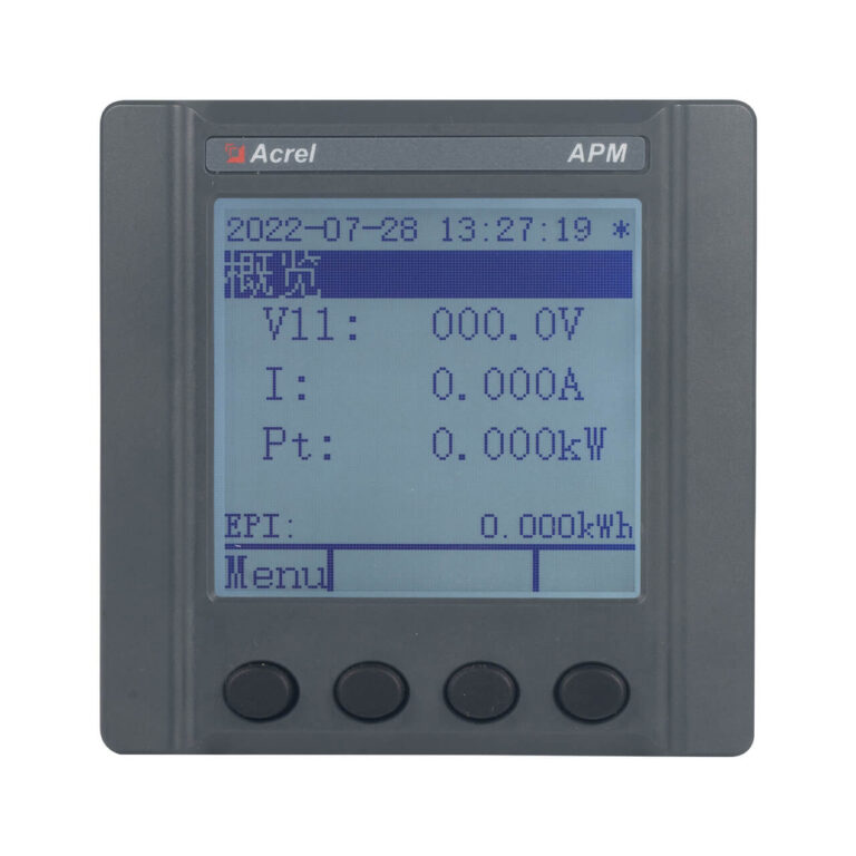
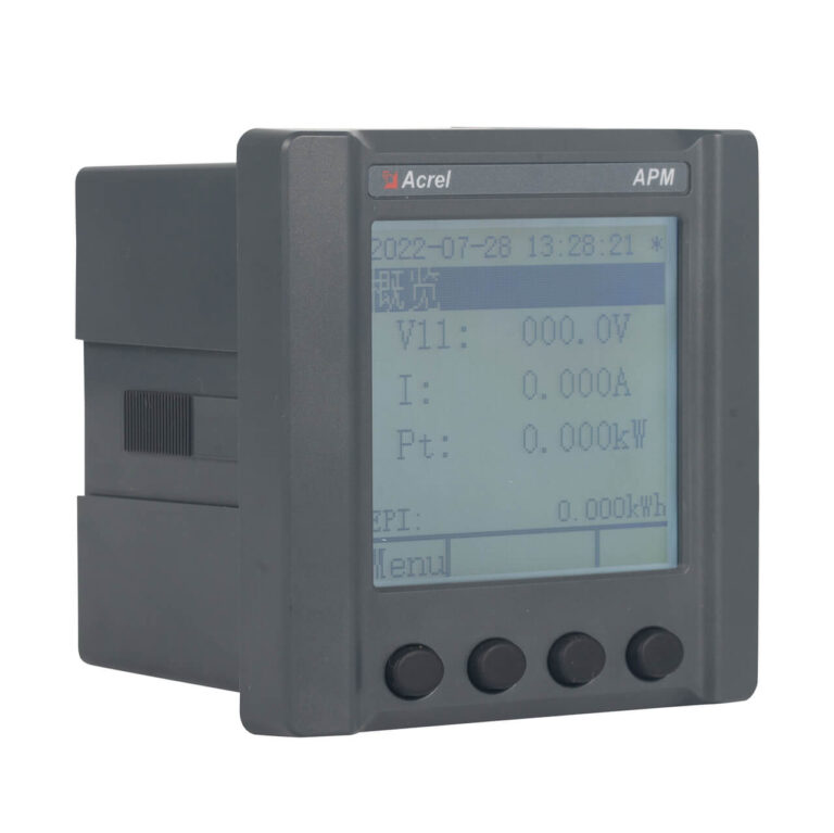
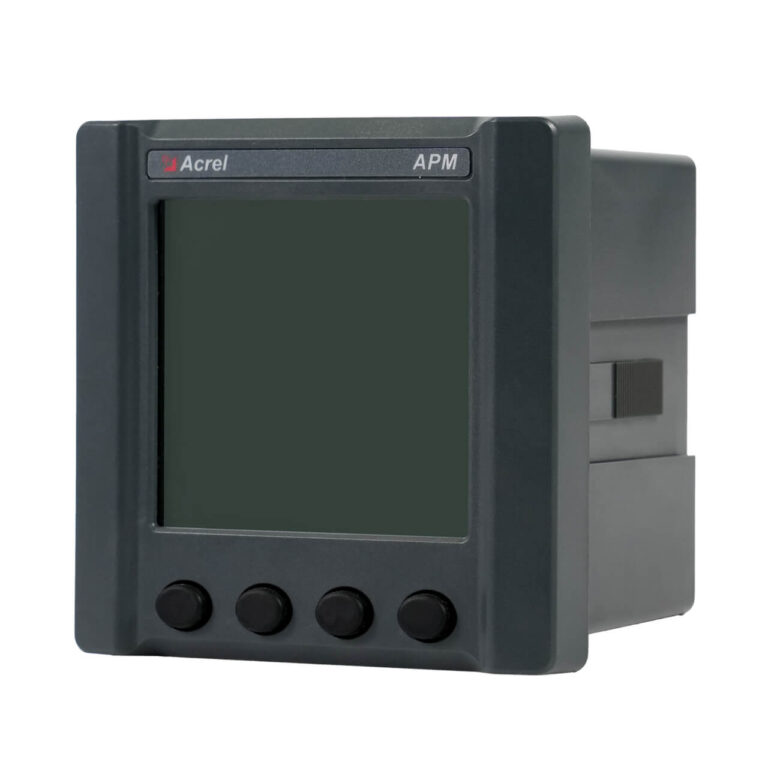
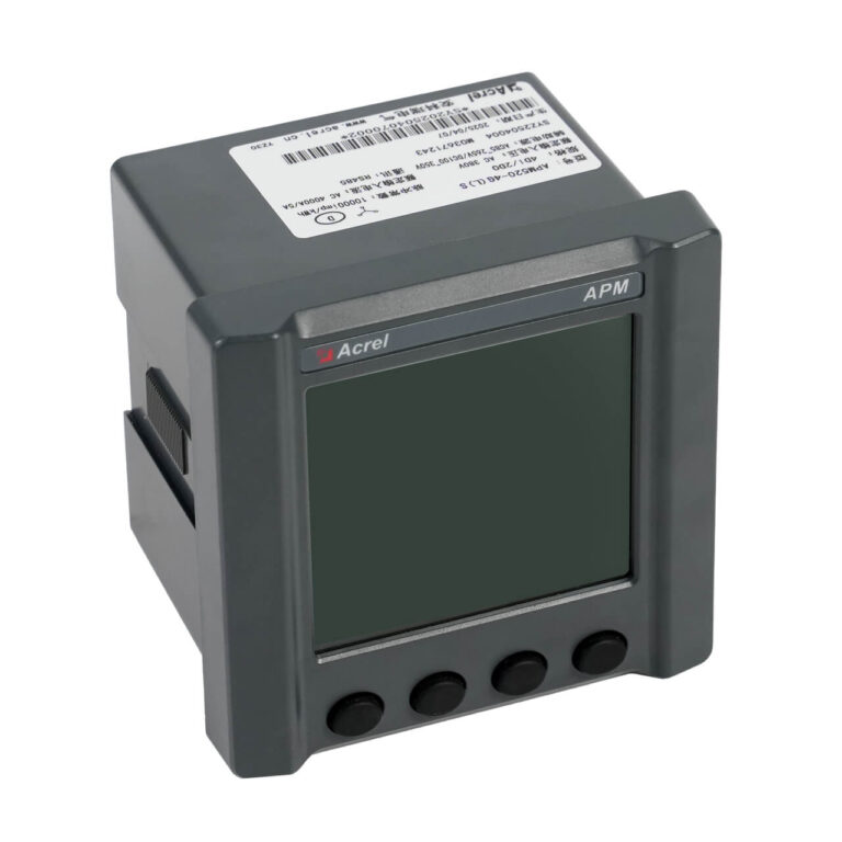
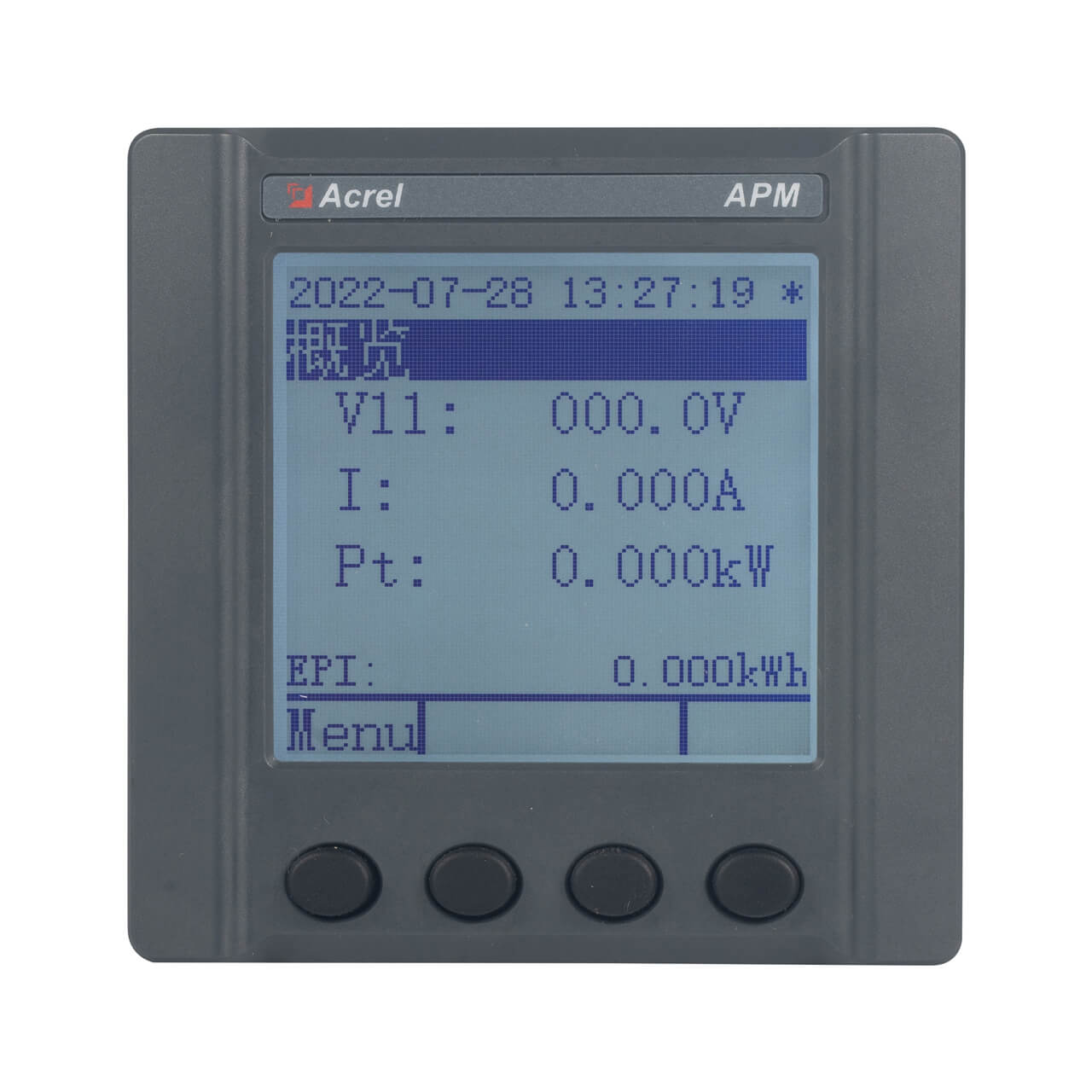
The APM520 is a 96mm form factor high-performance network power meter integrating full electrical measurement, high-precision energy metering, comprehensive power quality analysis, fault recording, event logging, and flexible network communication.
It is specifically engineered for critical power distribution systems requiring comprehensive monitoring and management of power supply quality. Utilizing a modular design, users can flexibly select expansion functions including temperature measurement (T), leakage monitoring (L), multi-tariff (F), Class 0.2S high-precision fault recording (S), WiFi, LoRa, and 4G wireless communication based on actual project requirements. The dot-matrix LCD display with switchable Chinese/English interface provides intuitive and convenient operation.
Highlight
Multi-Model Options
- Base: 4DI+2DO+2EP+1C (Modbus-RTU/DL/T645)
- K: 4DI+2DO expansion
- 2M: 2 analog outputs (4-20mA)
- T: 4 NTC temperature sensors
- L: 1 leakage current monitoring
- F: Multi-tariff energy
- S: Class 0.2S accuracy + fault recording
- CE: Ethernet communication
- 2C: 2nd RS485 port
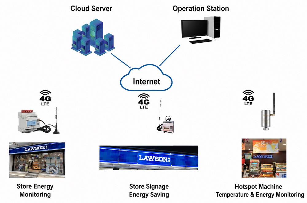
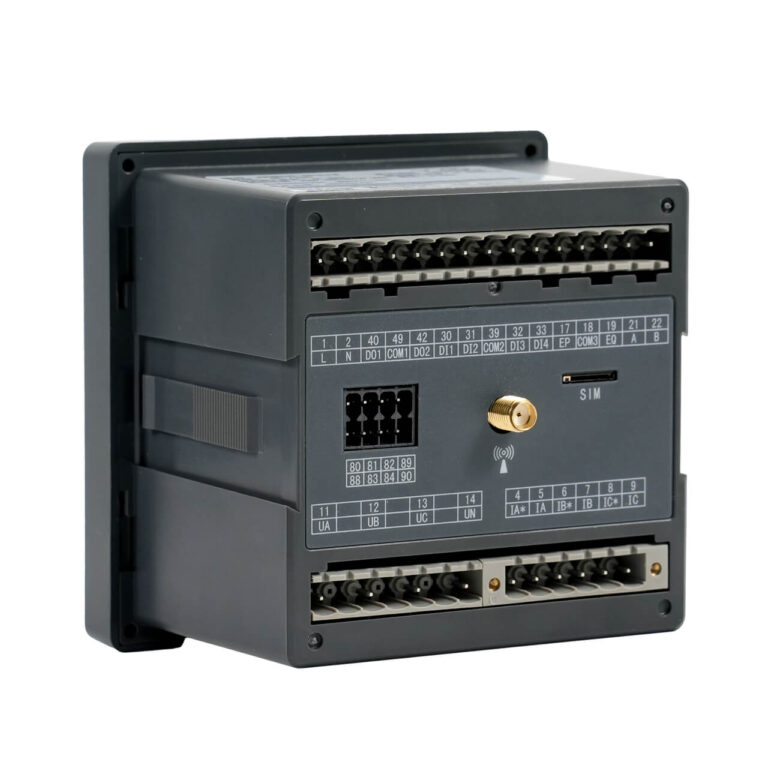
- WF/LR/4G: WiFi/LoRa/4G wireless
Wide Power Supply
- AC 85-265V / DC 100-350V wide range
- ≤15VA low power consumption
- Suitable for various industrial environments
High Accuracy
- Voltage/current: Class 0.2
- Active energy: Class 0.5S (0.2S with S option)
- 2-63rd harmonics, interharmonics, flicker
- Fault recording with waveform capture
Standard Outputs
- RS485 Modbus-RTU & DL/T645
- 2 pulse outputs (active/reactive)
- 2 relay outputs (5A)
- Dot-matrix LCD display
Function
| Measurement | Voltage: Phase, Line, Deviation, Angle Current: Phase, Neutral, Leakage (with L option) Power: Active/Reactive/Apparent (per phase + total) Power Factor: per phase + total, fundamental Frequency Temperature: NTC (with T option) |
| Power Quality | Harmonics: 2nd-63rd, THD, Odd/Even Interharmonics (with S option) Flicker (with S option): Pst, Plt Unbalance: Voltage, Current Sequence: Positive/Negative/Zero Waveform: Real-time display, Vector diagram Other: Peak coeff., K-factor, TIF |
| Energy & Demand | Four-quadrant Active/Reactive/Apparent Multi-tariff (with F option): 4 tariffs, 14 periods Demand: Real-time current/power, monthly max (with timestamp) Extreme Value: Monthly max/min V/I/P (with timestamp) Frozen Energy: Last 12 cycles energy, demand, current |
| Fault Recording (with S option) | Trigger Types: Swell/Sag/Interruption, Inrush, Harmonic, DI Capacity: 20 waveforms (10 pre + 10 post), 128 points/cycle |
| I/O & Alarms | Digital Inputs: 4DI base (dry contact), response <300ms Digital Outputs: 2DO base (NO, AC 250V/3A, DC 30V/3A) Analog Outputs (with 2M option): 2ch 4-20mA/0-20mA Alarms: 2 independent groups, 90+ alarm types, configurable threshold/delay/hysteresis Event Logging: 128 alarms + 128 DI/DO events (with timestamp) |
| Communication & Integration | Standard: 1x RS485, Modbus-RTU, DL/T 645-2007 Optional: 2nd RS485 (2C), Ethernet (CE), WiFi (WF), LoRa (LR), 4G (4G) Protocols: Modbus-RTU, Modbus-TCP (CE), DL/T 645-2007 |
Specification
| Parameter | Specification |
| Input Voltage | Rated: AC 57.7/100V, 63.5/110V, 230/400V, 400/690V (96 size); Overload: 1.2×/2×1s; Burden: <0.5VA/phase |
| Input Current | Rated: 1A(1.2A) or 5A(6A); Overload: 1.2×/10×1s; Burden: <0.5VA/phase |
| Measurement Accuracy | V/I: 0.2% (IEC 61557-12); Active Energy: Class 0.5S (GB/T 17215.321-2008), Class 0.2S with S option; Reactive Energy: Class 2 (IEC 62053-24); Frequency: ±0.02Hz |
| Harmonic Measurement | 2nd–63rd, accuracy: 1% (IEC 61557-12) |
| Fault Recording (S opt) | 20 waveforms (10 pre + 10 post), 128 points/cycle |
| Response Time | ≤200ms for V, I, P; ≤1s for energy |
| Auxiliary Power | AC 85–265V / DC 100–350V; Consumption: ≤15VA |
| Digital Inputs | 4DI base (dry contact), response <300ms |
| Relay Outputs | 2DO base, NO contacts, AC 250V/3A, DC 30V/3A |
| Analog Output (opt) | 2M module: 2ch 4-20mA/0-20mA |
| Communication | Standard: 1x RS485 (Modbus-RTU, DL/T 645-2007) |
| Optional: 2nd RS485 (2C), Ethernet (CE), WiFi (WF), LoRa (LR), 4G (4G) | |
| Temperature (T opt) | 4ch NTC temperature measurement |
| Leakage (L opt) | 1ch leakage current measurement |
| Display | Dot-matrix LCD, 128×64, Chinese/English switchable, white LED backlight |
| Operating Environment | Temp: -25~+65℃; Humidity: ≤95% non-condensing; Altitude: ≤2500m |
| Safety & EMC | Dielectric: AC 4kV/1min (power to signal); EMC: IEC 61000-4 Class IV |
| Mounting | Panel mount (cutout 88×88mm) |
| Dimensions | Bezel: 96×96mm; Case: 86.5×86.5×77.8mm |
| Ingress Protection | IP54 (front panel) |
| Standards Compliance | IEC 61557-12, IEC 62053-22/24, IEC 61000-4, GB/T 17215.321-2008, etc. |
Show More
Ordering Information
| Model Code | Description |
| APM520 | Base unit (4DI+2DO+2EP+1C) |
| APM520/CE | + Ethernet module (Modbus-TCP) |
| APM520/2C | + 2nd RS485 communication |
| APM520/K | + Extended DI/DO module (4DI+2DO) |
| APM520/2M | + 2ch analog output (4-20mA) |
| APM520/T | + 4ch NTC temperature measurement |
| APM520/L | + 1ch leakage current measurement |
| APM520/F | + Multi-tariff function |
| APM520/S | + Class 0.2S accuracy + Fault recording |
| APM520/WF | + WiFi wireless communication |
| APM520/LR | + LoRa wireless communication |
| APM520/4G | + 4G wireless communication |
Show More
Compatible Accessories
| Accessory | Description |
| Current Transformers | External CTs with secondary rating of 1A or 5A, accuracy Class 0.2S/0.5S optional |
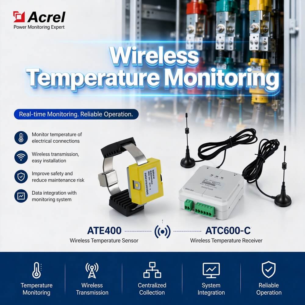
| NTC Temperature Sensors | For use with T module, measure cable joint or switchgear temperature |
| Leakage Current Transformer | For use with L module, monitor ground leakage current |
| RS485 Repeater | For extending RS485 communication distance beyond 1000m |
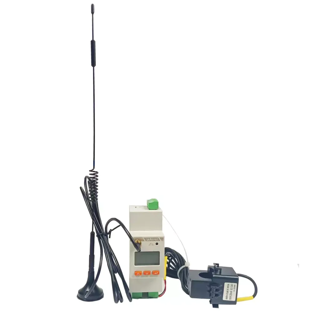
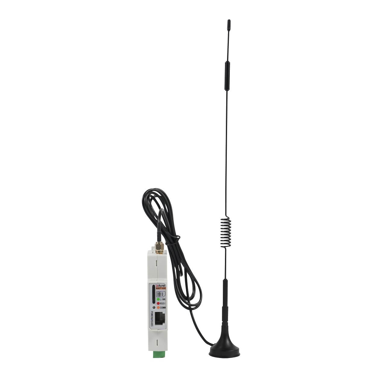
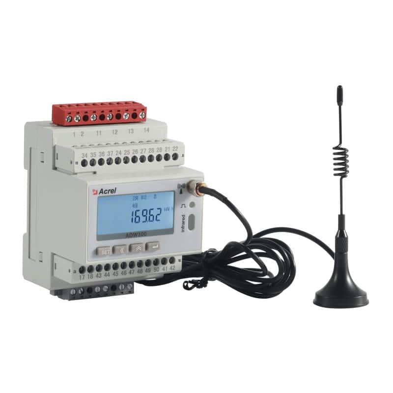
| Antenna | For use with wireless modules (WF/LR/4G), signal enhancement |
FAQ
APM520 is a 96mm size meter with base config of 4DI+2DO+2EP+1C; APM521 has slightly different base config, and APM520 offers richer wireless options (WiFi/LoRa/4G) and temperature/leakage monitoring.
With S option, active energy accuracy improves from Class 0.5S to Class 0.2S (GB/T 17215.321-2008), adds fault recording for swells/sags/interruptions/inrush currents, plus interharmonic and flicker measurement.
Enter “Input Setting” menu, set “U Rating1” (PT) and “I Rating1” (CT). Display shows primary-side values automatically.
Go to “Communication Settings” → “Wireless Settings” submenu. LoRa channel/frequency can be configured; WiFi/4G require SIM card or network config via keypad or communication interface.
Configure trigger conditions in “Recording Settings” menu: inrush current threshold, swell/sag/interruption thresholds, current/voltage harmonics, DI trigger. When conditions met, meter records 10 pre + 10 post cycles.
Standard RS485 supports Modbus-RTU and DL/T 645-2007; Ethernet module supports Modbus-TCP; wireless modules support Modbus data over respective wireless protocols.
Default is 0001, changeable in “System Settings”. Contact technical support if forgotten.
Summary
The APM520 network power meter offers a comprehensive power monitoring solution for critical power distribution systems. Its high-precision measurement (Class 0.5S/0.2S) , in-depth power quality analysis (harmonics, interharmonics, flicker) , fault recording capability , and modular expandability make it suitable for a wide range of applications from smart distribution to industrial automation and data centers. By consolidating multiple functions into a single device, it reduces installation complexity, saves panel space, and provides a unified data source for energy management systems. With flexible communication options including RS485, Ethernet, WiFi, LoRa, and 4G, the APM520 integrates seamlessly into modern digital power distribution networks.