
Independent AC/DC Energy Monitoring for Shared Telecom Towers, Base Stations, and Distributed Telecom Networks
Telecom RMS at a Glance
What Is a Telecom Remote Monitoring System?
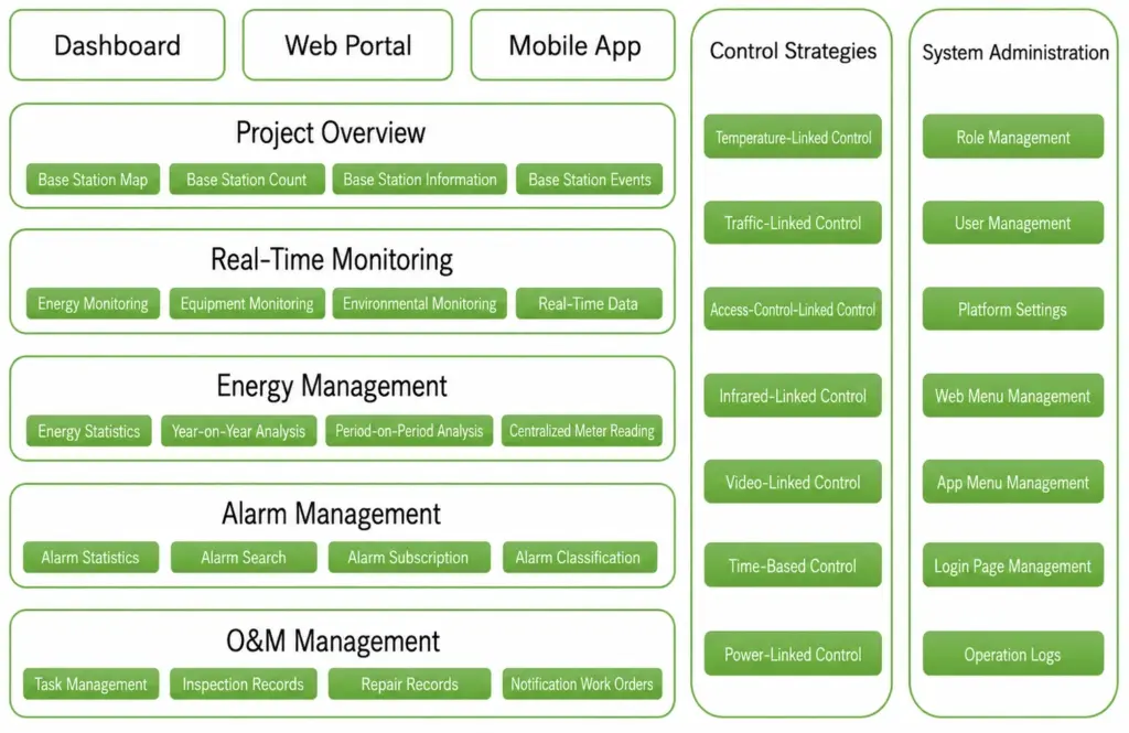
A Telecom Remote Monitoring System (RMS) is a site-level solution for telecom AC/DC power monitoring that collects, processes, stores, and remotely transmits electrical and operational data from telecom towers and base stations.
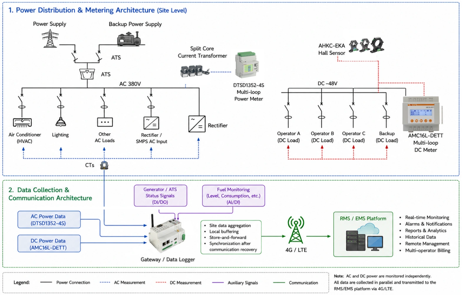
For shared telecom sites, a complete RMS should provide more than total site energy consumption. It should enable independent telecom energy monitoring for each operator, while also providing visibility into the common AC power system, -48V DC distribution, generator, ATS, fuel level, and other critical site information.
A typical data flow is:
AC/DC Meters & Sensors → Gateway / Data Logger → 4G/LTE → RMS / EMS Platform
What Can a Telecom RMS Monitor?
| Monitoring Area | Typical Monitoring Points | Purpose |
| AC Power | Grid, generator, AC feeders | Site-level energy monitoring |
| Rectifier / SMPS | AC input and/or DC output | Power-path visibility |
| -48V DC | Common DC bus and operator branches | Independent operator energy measurement |
| Generator | Running status, operating signals | Generator operation monitoring |
| ATS | Transfer status and signals | Power-source status monitoring |
| Fuel | Fuel level, refill, abnormal drop | Fuel management |
| Communication | RS485, Ethernet, 4G/LTE | Remote data transmission |
| Edge Data | Local buffering and storage | Data continuity during communication loss |
Who Needs a Telecom RMS?
A telecom RMS is particularly suitable for:
- Tower companies (TowerCos)
- Shared telecom infrastructure
- Multi-operator base stations
- Remote macro base stations
- Generator-supported telecom sites
- Large distributed telecom networks
Why Shared Telecom Sites Need Independent Energy Monitoring
One Site, Multiple Operators, One Common Power System
Challenge 1 — Shared Infrastructure, Separate Energy Responsibility
Multiple operators may share the same grid connection, generator, rectifier system, and -48V DC bus, but their energy consumption still needs to be measured and allocated separately. Without independent telecom power metering for each operator, site owners may have to rely on estimated ratios or manual calculations, making energy settlement less transparent and more difficult to verify.
Challenge 2 — AC Monitoring Alone Is Not Enough
Monitoring only the grid or generator AC input shows the total energy entering the site, but it does not show how much power is consumed by Operator A, Operator B, or Operator C on the -48V DC side. Effective telecom AC/DC power monitoring therefore requires both AC-side measurement and independent DC branch metering.
Challenge 3 — Multi-Circuit -48V DC Measurement Is Difficult
A shared telecom DC power system can contain several high-current -48V DC branches within limited cabinet space. Using separate single-circuit meters for every branch increases device quantity, wiring, installation time, and communication addresses. A compact multi-circuit DC power monitoring system is therefore more suitable for operator-level measurement.
Challenge 4 — Generator, ATS and Fuel Data Are Fragmented
Generator operating status, ATS signals, fuel level, and electrical metering data may come from different devices or interfaces. When these data sources are monitored separately, operators lack a unified site-level view and may need additional manual checks during power-source switching or generator operation.
Challenge 5 — Remote Sites Need Reliable Data Continuity
Telecom sites often depend on 4G/LTE communication for remote monitoring. Temporary network interruptions can create gaps in historical data if information is transmitted only in real time. The site gateway/data logger should therefore support local buffering, store-and-forward, and automatic synchronization after communication is restored.
How Telecom RMS Solves These Challenges
| Telecom Site Challenge | RMS Solution |
| Multiple operators share the same power infrastructure | Independent -48V DC branch metering |
| Total AC consumption cannot identify operator usage | AC + DC multi-circuit monitoring |
| Limited cabinet space and many DC circuits | Multi-circuit DC meters + Hall sensors |
| Generator, ATS and fuel data are separated | Centralized gateway/data logger |
| 4G/LTE interruptions cause data gaps | Local data buffering and synchronization |
Recommended Telecom RMS Architecture
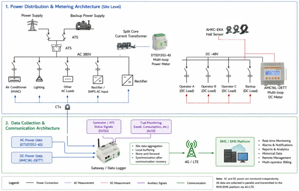
Complete System Architecture
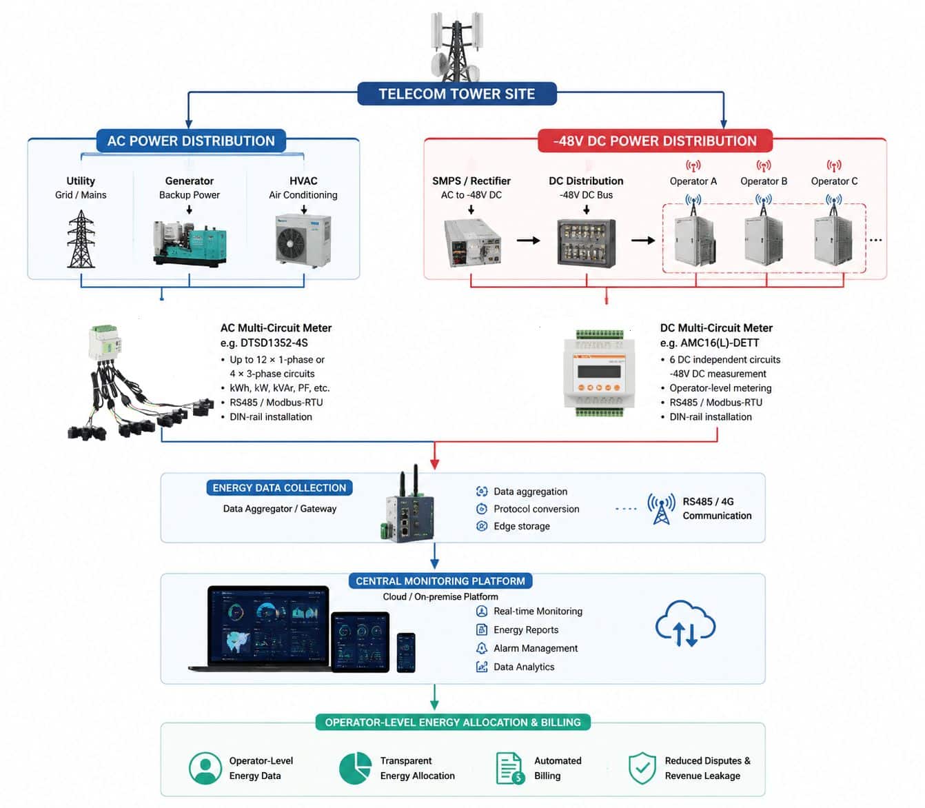
AC Power Monitoring
Grid / Generator → AC Distribution → CTs → Multi-Circuit AC Energy Meter
For AC-side telecom rectifier monitoring, the AC monitoring layer can cover:
- Utility input
- Generator output
- AC feeders
- Rectifier / SMPS AC input
- HVAC
- Lighting
- Other auxiliary loads
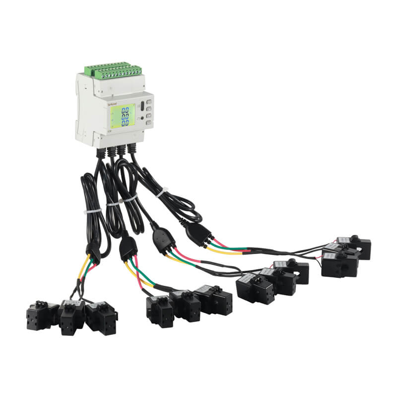
For compact multi-circuit AC monitoring, an external CT-based telecom power meter can be used to measure several circuits within the same cabinet.
-48V DC Multi-Operator Monitoring
-48V DC Bus → Operator A / B / C → Hall-Effect Sensors → Multi-Circuit DC Energy Meter
This is the key measurement layer for -48V DC power monitoring at shared telecom sites.
Each operator branch can be measured independently to provide:
- Voltage
- Current
- Power
- Energy consumption
- Operator-level energy data
Reserved channels can also be considered for future expansion.
Generator, ATS and Fuel Monitoring
The RMS architecture can also collect available:
- Generator status
- ATS status
- Fuel level
- Fuel refill information
- Abnormal fuel-drop signals
These signals can be integrated with AC/DC energy data through a common gateway/data logger.
Communication and Edge Data Logging
AC/DC Meters + Generator/ATS + Fuel Sensors → Gateway → 4G/LTE → RMS/EMS
The gateway performs three key functions:
- Collects data from field devices
- Stores data locally when required
- Transmits site information to the centralized RMS/EMS platform
How to Design the Right Telecom RMS Configuration
| RMS Component | Main Function | Typical Equipment |
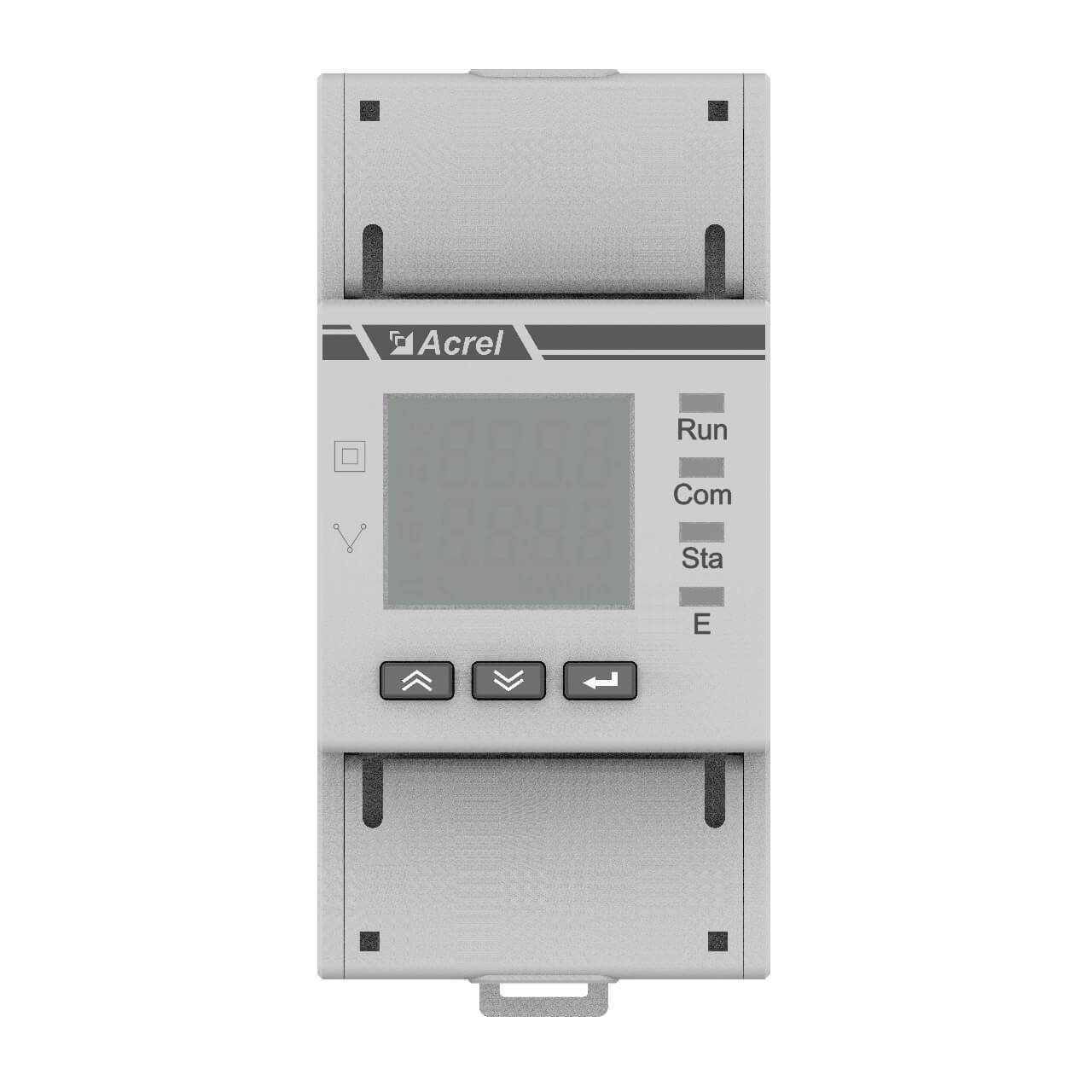
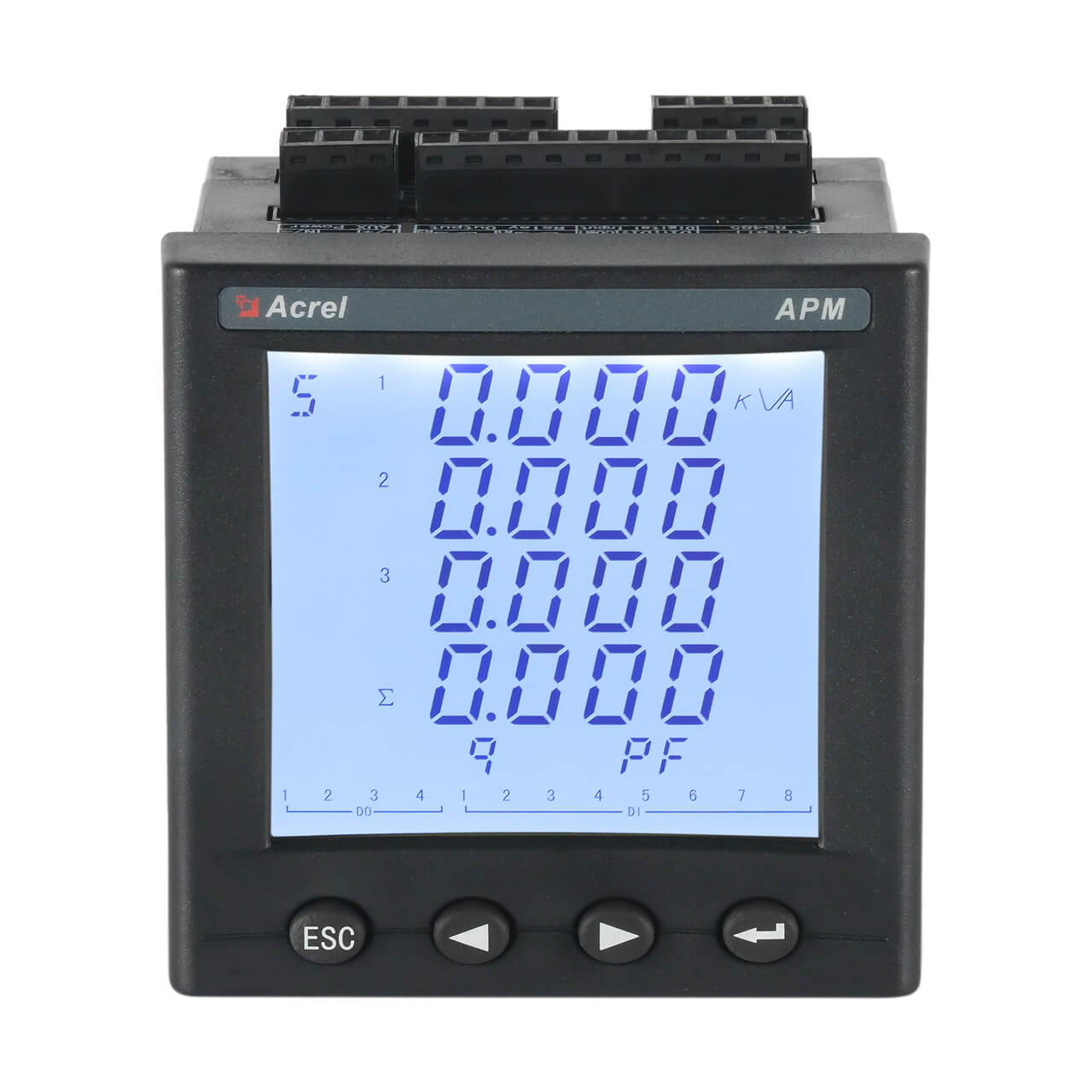
| AC Energy Metering | Grid, generator and AC feeder monitoring | DTSD1352-4S / AMC200L-8E3 + CTs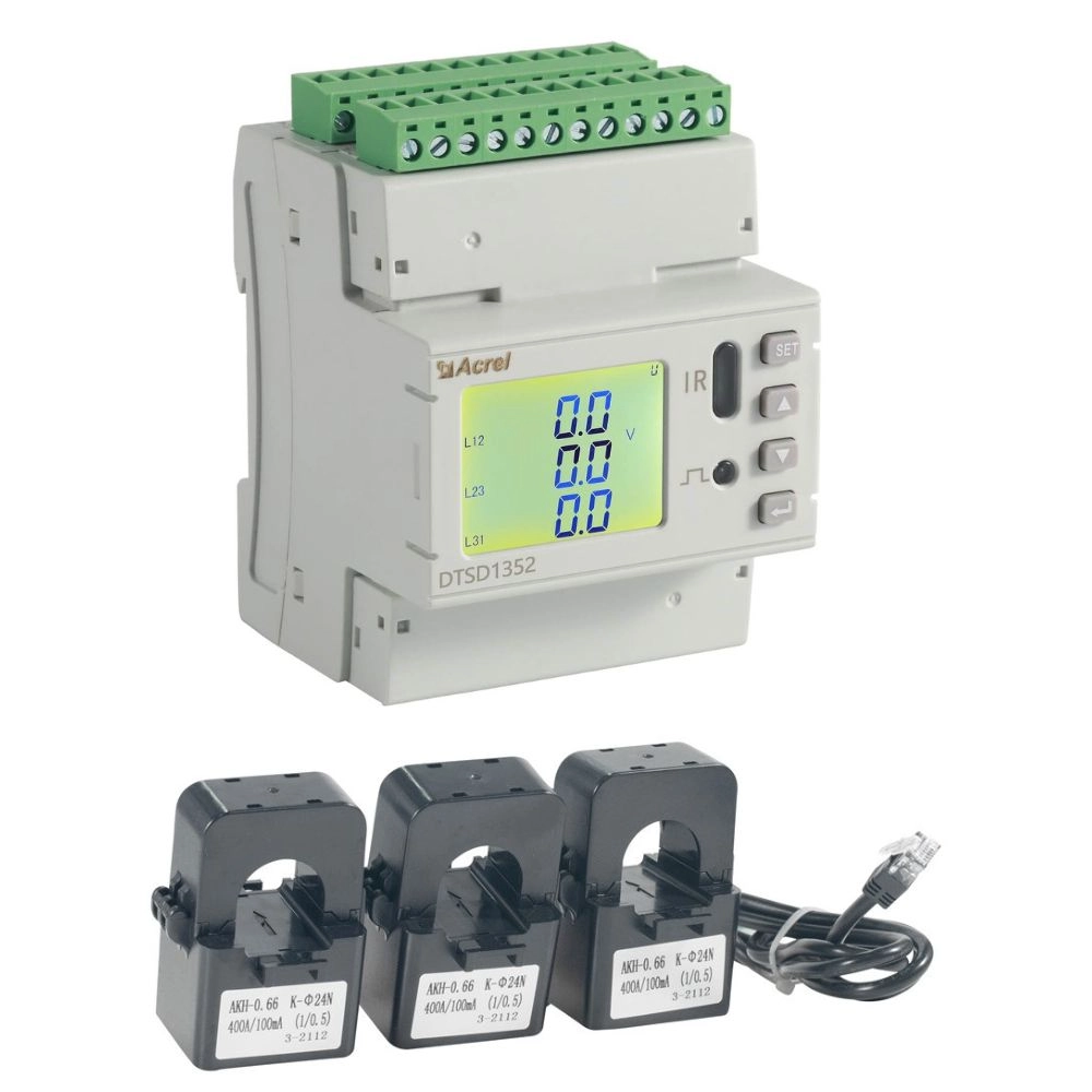 |
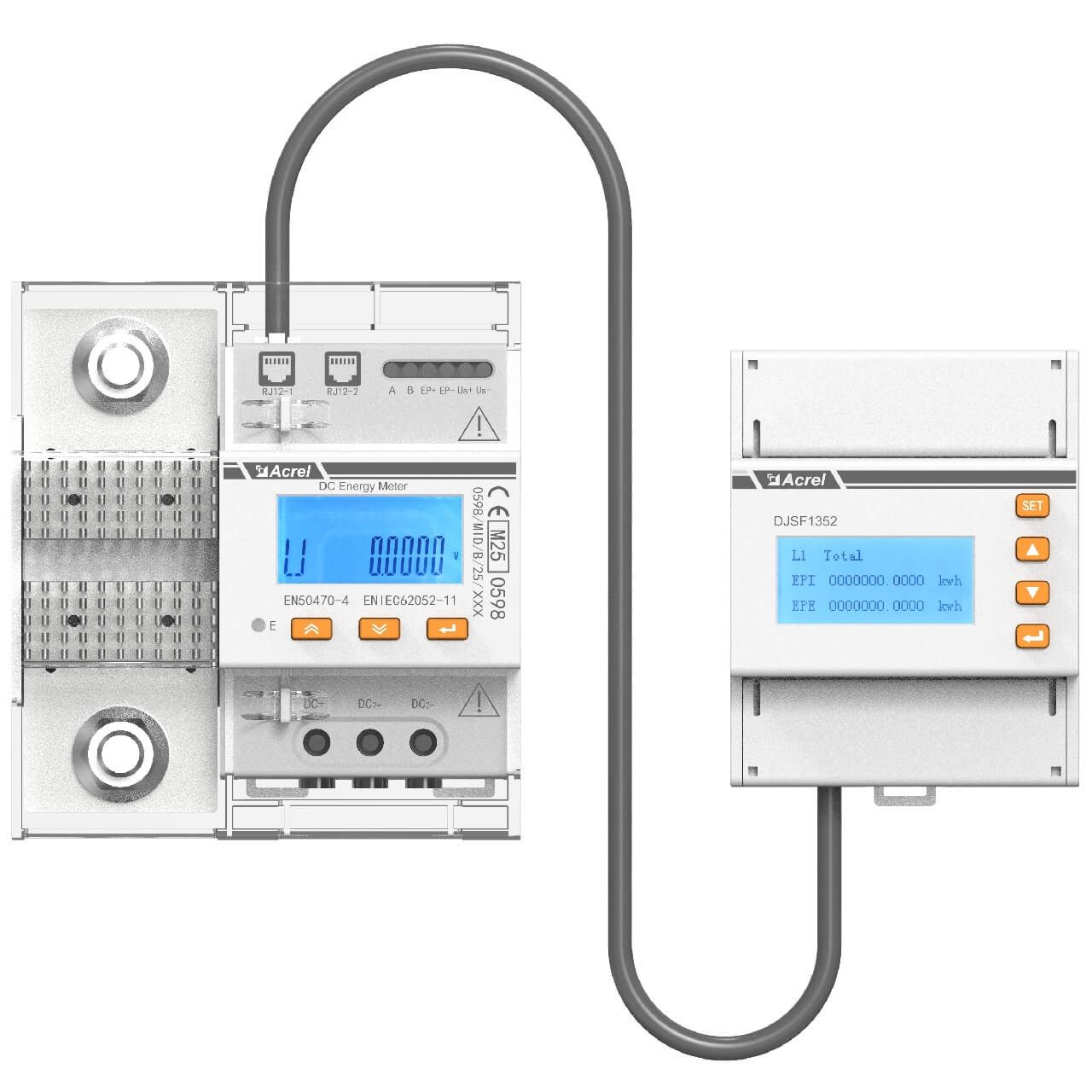
| DC Energy Metering | Independent -48V DC branch monitoring | AMC16L-DETT / AMC200L-12DE + Hall sensor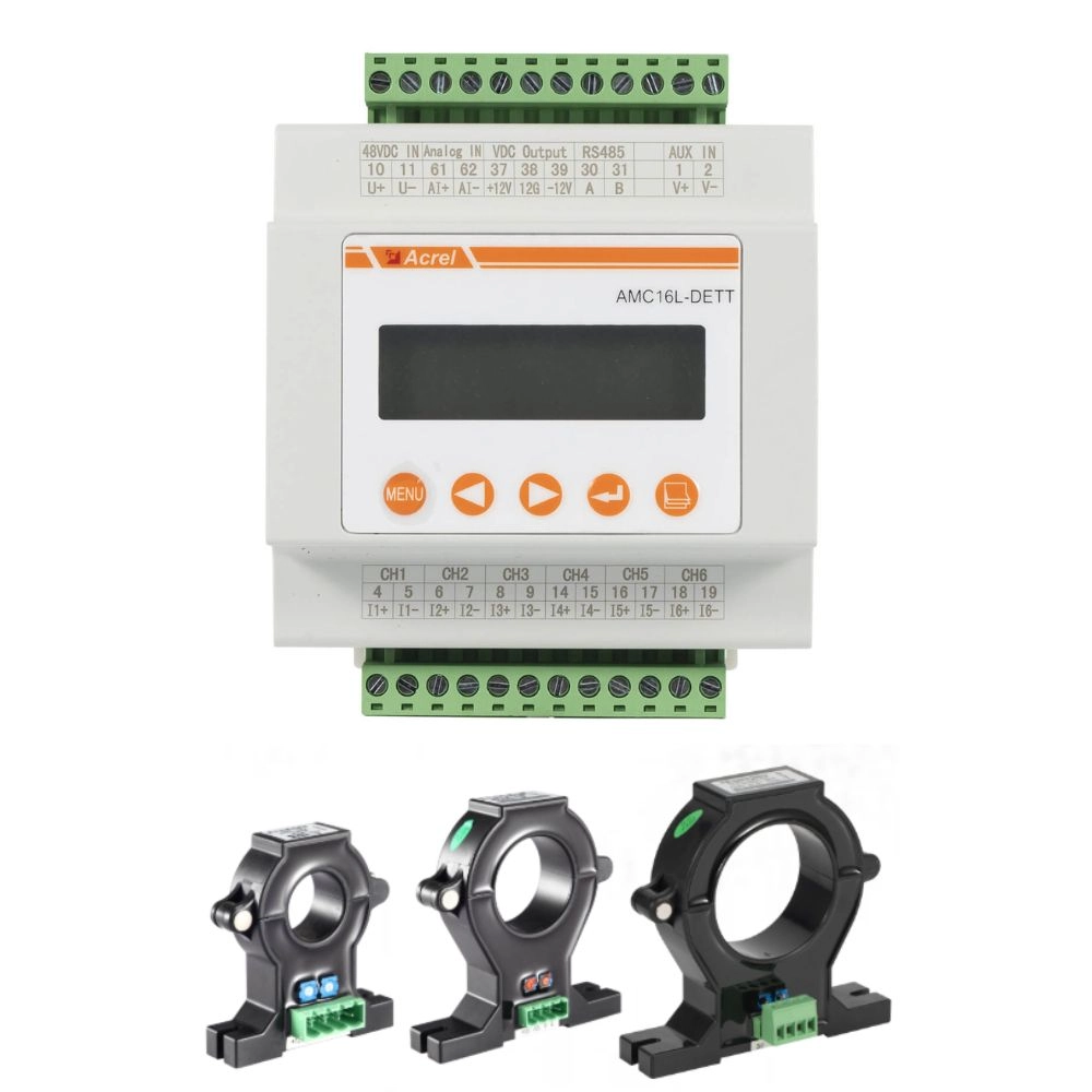 |
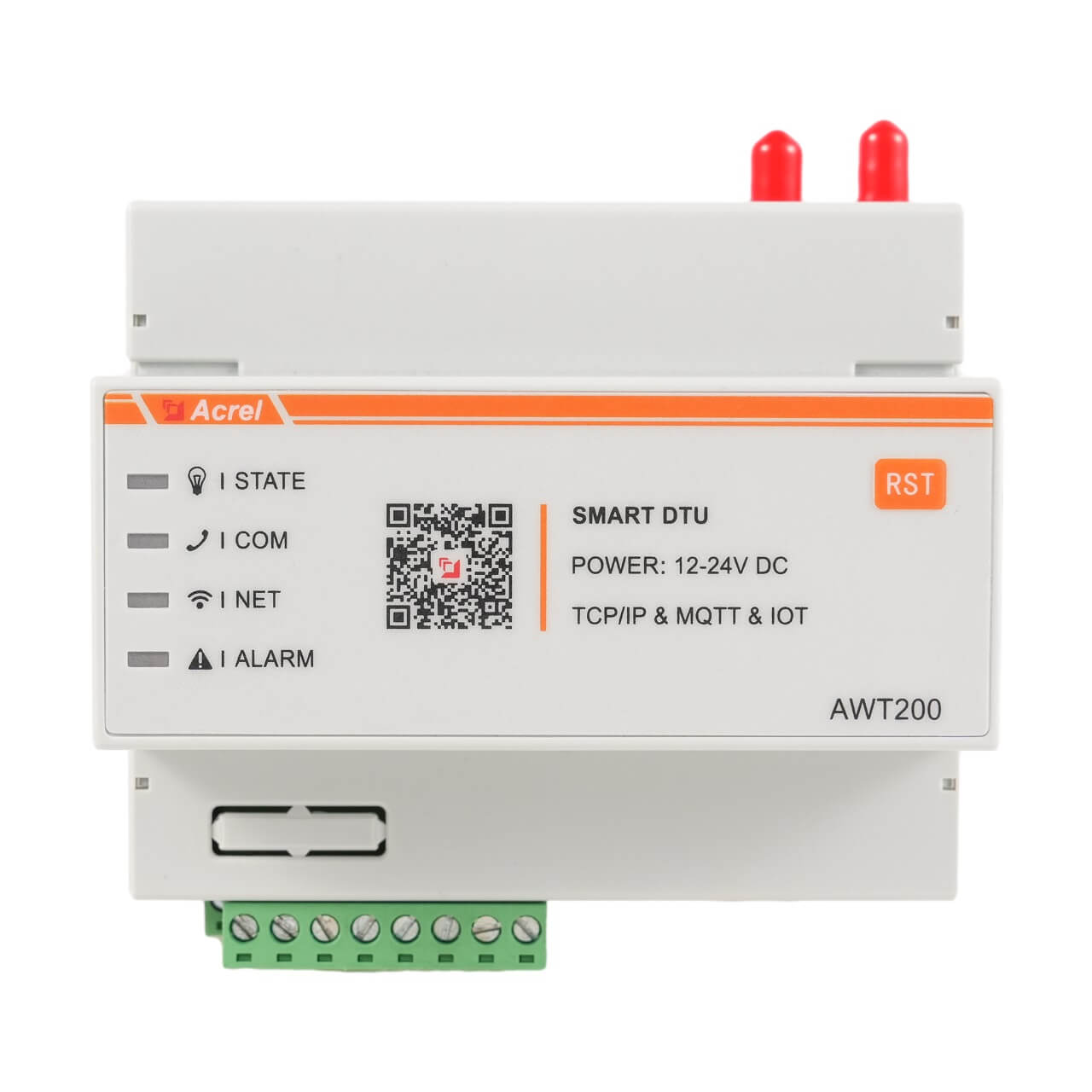
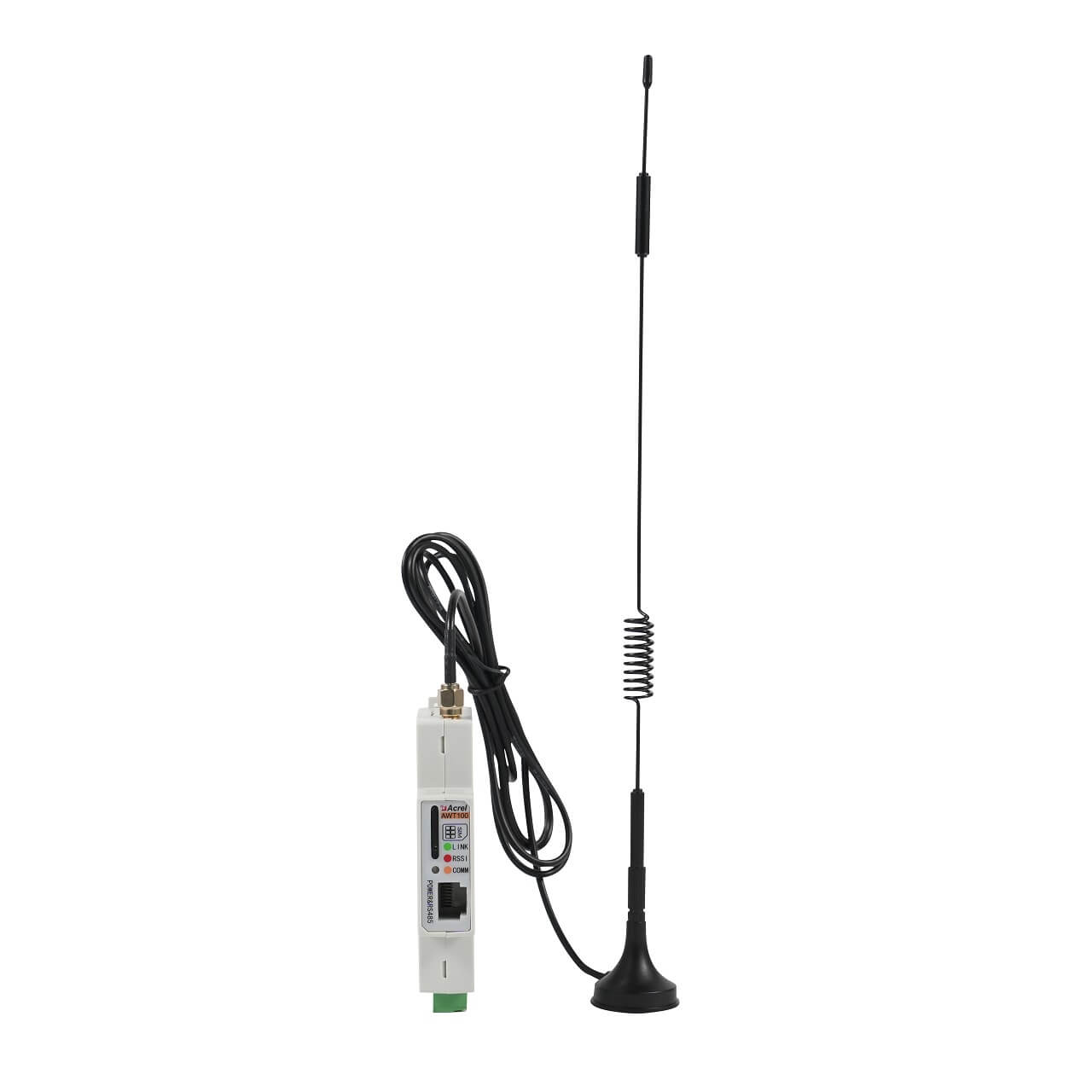
| Gateway / Data Logger | Data acquisition, local storage and communication | Industrial gateway / data logger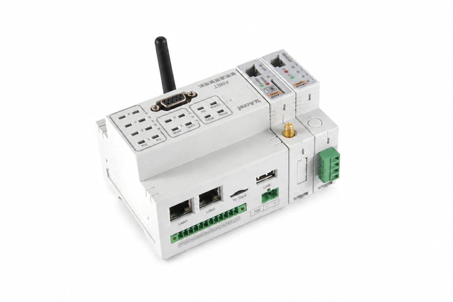 |
| Site Status & Fuel Monitoring | Generator, ATS and fuel monitoring | DI/AI interfaces + fuel sensor |
| Power Distribution & Protection | Power supply, circuit isolation and electrical protection | MCB / MCCB, terminal blocks, power supply, surge protection, etc. |
| RMS Site Box / Enclosure | Integrates meters, protection, wiring and communication devices | Project-specific enclosure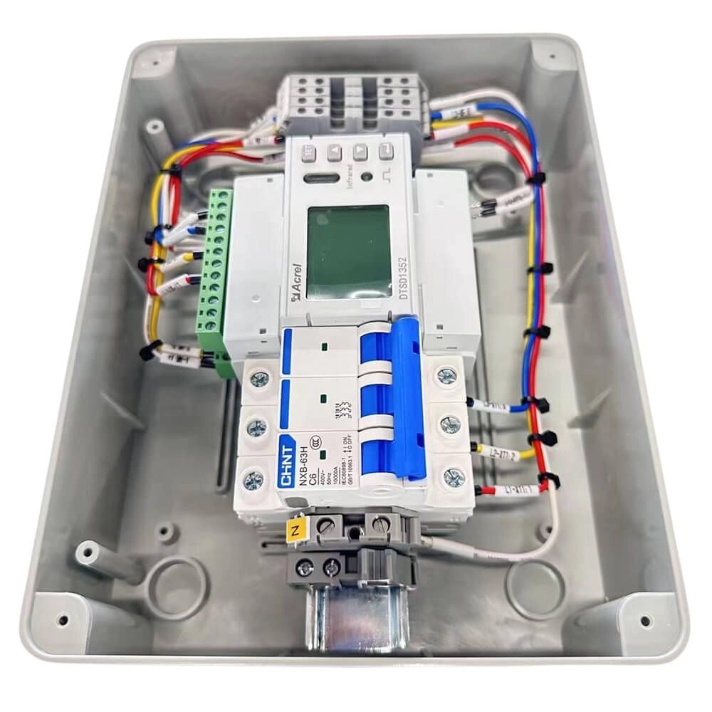 |
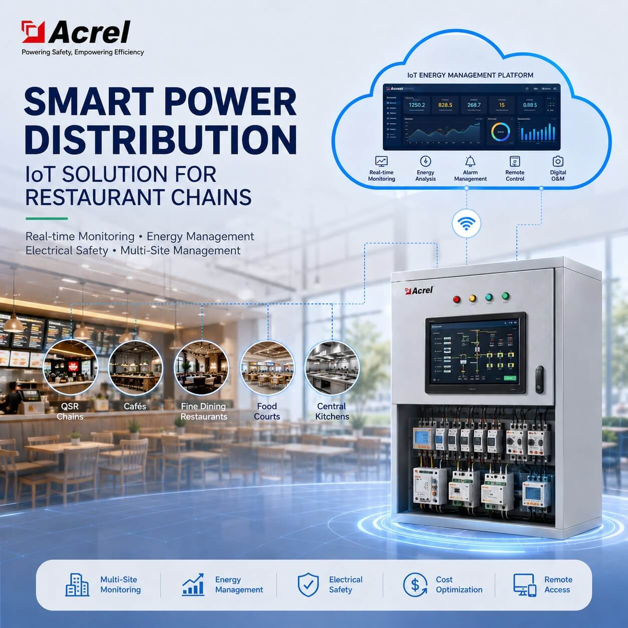
RMS Site Box: Integrated Power Distribution and Monitoring
The RMS Site Box provides an integrated enclosure for power distribution, circuit protection, energy metering, data acquisition, and communication equipment at the telecom site.
Typical Applications
Shared Telecom Towers
For TowerCos operating sites shared by two or more telecom operators, RMS can provide independent operator-level energy measurement and centralized site monitoring.
Remote Macro Base Stations
Centralized telecom power monitoring reduces dependence on manual meter reading and improves visibility across geographically distributed sites.
Generator-Supported Telecom Sites
As a smart telecom energy solution, RMS can combine energy metering with generator, ATS and fuel monitoring to provide a more complete view of site operation.
TowerCo Multi-Site Networks
A centralized tower energy management system can help TowerCos compare sites, monitor operator consumption, identify abnormal energy trends, manage distributed telecom infrastructure, and support telecom energy efficiency.
Proven Telecom RMS Project Experience
Philippines — EdgePoint RMS Project
Acrel supplied 6000+ sets of DTSD1352-4S for the EdgePoint RMS telecom base station project in the Philippines.
Application: Telecom Base Station Power Monitoring
Monitoring: Multi-circuit AC energy measurement
Key Value:
- Compact installation
- Reduced meter quantity
- Centralized site data collection
- Scalable deployment across distributed telecom sites
Madagascar & Chad — Telecom Base Station DC Monitoring
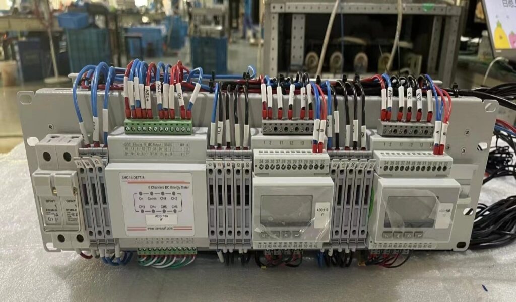
Acrel supplied 3,600+ sets of AMC16-DETT for telecom base station projects in Madagascar and Chad.
Application: -48V DC Telecom Power Monitoring
Monitoring: Multi-circuit DC energy measurement
Key Value:
- Independent monitoring of multiple DC branches
- Improved visibility of telecom DC loads
- Compact multi-circuit measurement
- Suitable for large-scale distributed deployment
Frequently Asked Questions
A Telecom RMS is a site-level system that collects and remotely transmits electrical and operational data from telecom towers and base stations, including AC/DC energy, generator, ATS and fuel-related information.
For -48V DC power monitoring, each operator’s branch can be measured independently using a multi-circuit DC energy meter with suitable Hall-effect current sensors.
Yes. In telecom AC/DC power monitoring, AC multi-circuit meters can monitor grid, generator and feeder circuits, while DC multi-circuit meters monitor -48V DC operator branches.
Yes, provided sufficient measurement channels and interfaces are reserved during system design.
A suitable gateway/data logger can buffer site data locally and synchronize the stored records after communication is restored.
Yes, available generator and ATS signals can be collected through the gateway/data logger as part of the overall site monitoring architecture.
Yes. Fuel-level and related fuel-monitoring signals can be integrated according to the selected sensor and gateway configuration.
Integration depends on the customer’s northbound requirements. APIs, MQTT, third-party device integration and other interfaces should be confirmed during system design.
Related Telecom Solutions
Explore more Acrel resources related to telecom site monitoring and multi-circuit energy management:
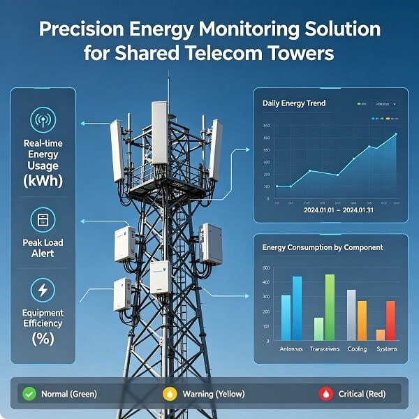
- Precision Energy Monitoring Solution for Shared Telecom Towers — AC and -48V DC multi-circuit measurement for shared telecom infrastructure.
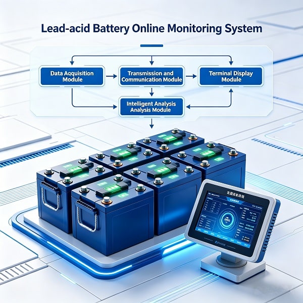
- Lead-Acid Battery Online Monitoring System — Online monitoring solution for lead-acid battery status and condition in telecom power systems.
- Telecom Tower AC/DC Energy Metering for Multi-Operator Billing — AC and -48V DC multi-circuit energy metering for shared telecom towers and independent operator billing.
Build the Right RMS for Your Telecom Sites
Every telecom site has different power distribution, operator configuration, circuit quantity, current range and communication requirements.
Acrel can help you define the appropriate AC/DC metering architecture, multi-operator monitoring configuration, gateway communication structure, and RMS integration approach for telecom energy management.
Send us your site information:
- Number of telecom operators
- AC circuit quantity
- DC circuit quantity
- AC/DC current range
- Generator and ATS requirements
- Fuel monitoring requirements
- Existing RMS/EMS platform
- Communication method
Your telecom site configuration may be different from the architecture above? Send us your site details and our engineers can help you evaluate the appropriate RMS configuration.